External RAM

I found a big mistake.  The pinout I had used for the design has the SPI pinout wrong.  This means that the External RAM and the Port expander will not work until I fix this issue.  So, I found an online layout image that shows the flash chip as well as the pins.  I used esptool.py to request the flash ID.  The Flash ID manufacturer code is C8 and the device code is 4016.  Using Google, I found this to be the GD25Q32 made by GigaDevice.  This is a 4MByte spi/qspi flash chip.  I looked up the datasheet and found the following pinout.

1 CS#-------VDD   8
2  SO|     |Hold# 7
3 WP#|     |SCLK  6
4 VSS-------SI    5

CS#.....Active Low Chip Select
SO......Serial Data Output/ IO1 (Quad/Dual IO)
WP#.....Active Low Write Protect/IO2 (QuadIO)
SI......Serial Data Input/IO0 (Quad/DualIO)
SCLK....Serial Data Clock
Hold#...Active Low Hold/IO3 (QuadIO)
VDD/VSS.Power Connections

Looking at the ESP-12E Module layout, I found the following connections by tracing the tracks:

Flash CS# is connected to Pin 9 — No Change

Flash SO is connected to Pin 10 — No Change (MISO)

Flash IO2 is connected to Pin 11 — Requires a Change

Flash SI is connected to Pin 14 — Requires a Change (MOSI)

FLash SCLK is connected to Pin 12 — Requires a Change

Flash IO3 is connected to Pin 13 — Requires a Change

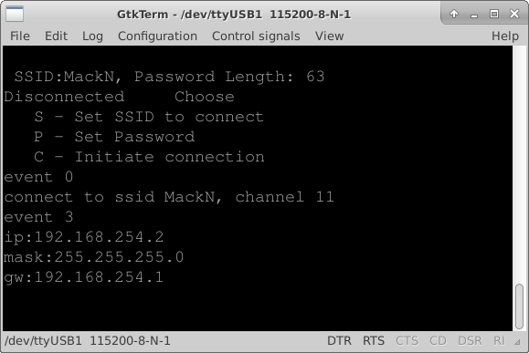
I also discovered that if I want to use the Built in SPI Chip selects, I need to use GPIO0(CS2) or GPIO15(HSPI_CS).  TxD is CS1 which is a conflict for testing so I can’t use CS1.  I found this in esp8266 datasheet.

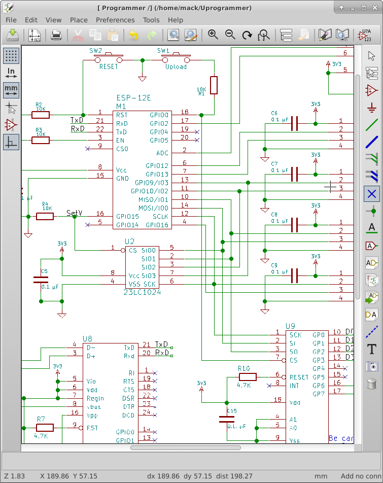
To fix the pinout on the schematic, I went into the library editor and just changed the pin numbers. I left the pin order in place for the schematic.

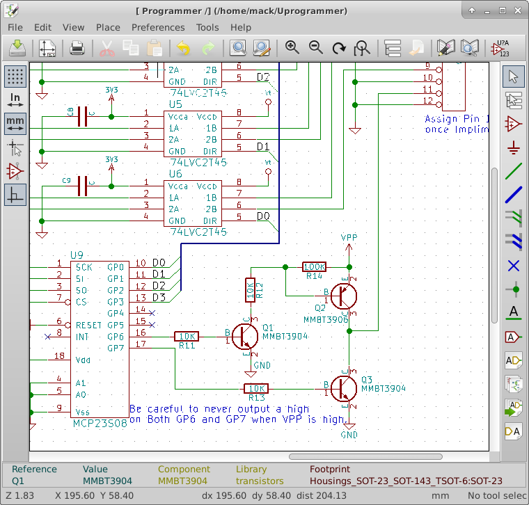
For the Chip Selects, I connected the RAM CS# to GPIO15(HSPI_CS) and the port expander to GPIO0(CS2).

I have some other schematic changes to make, I am still considering changing to the CH340G USB serial bridge.  The problems that I have had have given me reason to consider not using it.  I may have a faulty chip, I will test with another one, and if the problem goes away, I will feel more confident changing to the less expensive chip.

I have added the SPI and SPI overlay library code to the project source. No functionality has changed, so I am not uploading the code to GitHub yet.

HSPIconnections

Simple Serial Firmware V00B

This week was focused on software.

I did a little research on my problem with the serial upload tool failing.  I found that I could update to a newer kernal that had been backported into the Ubuntu repository.  This kernel had the serial issues fixed.  So my vertual machine Lubuntu kernel is now version 3.19.0-30-generic.  Also, I wanted to try Windows 10 before installing the update on my wife’s computer.  I downloaded a copy from Microsoft and installed without a license key.  This is how you do a trial install.  You can go back and install a license key later.  With the new kernel and the new version of VirtualBox, programming the Esp-12E became very easy.

I have been using esptool.py on my circuit with no problems.  With the NodeMCU board that has the CH340G USB to serial chip still doesn’t work without modifying esptool.py. This is making me rethink changing to the CH340G chip because I just want it to work for someone that is developing new code.

I added a menu structure to the file simple_serial.c.  I copied some code out of uart.c that echos back what was sent.  I got that working pretty quickly.  Then I started reacting to the characters being received. I simplified the receive routine and passed the received character to the user interface function that I named simple_config_ui.  The user interface is implemented as a simple state machine that changes state based on the received character. I will use this menu structure to start testing the hardware such as writing and reading from the ram, toggling individual outputs, reading inputs, and setting the high voltage output level.

Remember the software as it currently stands is on GitHub.com.  Just click the firmware on GitHub link at the top or the right side bar on this page.  The software is functional and allows the user to connect to a WiFi access point by setting the SSID and Password through a serial port terminal.

TermnalConnected

Hello World Firmware V0A

I have finally created a “Hello World” project that works with the Espressif IOT API.

First, in the upper right hand side of this page is a link to the GitHub repository for this project firmware. The general rule for version systems is that you only commit if the code is runnable.  I hope to break the code up into small enough chunks that I won’t get a majorly broken version in the repository, however things happen. If I get stuck, I’ll commit broken code to the repository to keep it current with these blog postings.  GitHub maintains Versions, I’ll try to name each commit in a way that ties back to the current blog entry.  The current commit is the same as the post title, “Hello World Firmware V0A”

Things happened again,  I did a security update on my OS and the esptool.py firmware uploader stopped working altogether.  I did a quick search online and found that the pyserial library started failing with this update.  So I figured out how to roll back to the previous version of the OS kernel and I could get the firmware upload to work.

I copied the AT firmware project into the app directory and ran the gen_misc.sh script file to configure the libraries.  I had some problems with this and I feel I need to know more about how the makefile works.  The gen_misc.sh (gen_misc.bat for windows users) creates a file with the needed libraries for the project.  For GitHub I ended up moving the project to the folder named UProgrammer-Firmware in the same folder that the app folder was in.

I deleted the AT firmware files from the project directory, keeping the user_config.h file in the include folder. I then created a new user_main.c file that just set up the serial port to 115200 baud and sent the text “Hello World” out the serial port from the user_init() function.  This worked and I wanted to do something a little more in depth of the API functionality.  So I started a timer that calls my code called user_state() once every second.  I set up this function to send “Hello World” over the serial connection on the second call of it.  I also removed the sending “Hello World” from the user_init() function.  The function user_init() is called once during boot up of the processor.

I also added the commands to connect to my wifi network.  I verified this by using a utility to see what devices were connected to my network.  When I saw the name espressif for one of the devices, I knew it was connected.  I took one more step and added a new file called wifi.c and a new file wifi.h to the project.  To the file wifi.c, I copied a function from the API documentation that reports connection status changes to the serial connection.  I changed which UART is used so it would report back over the serial connection.  I put the prototype for the function in wifi.h.

Finally, I created a file called simple_serial.c and another file called simple_serial.h.  I plan on moving the initialization code into simple_serial.c to clean up the user_init() function.  I also plan on creating a simple text interface for configuring the connection details.

On the hardware side, I couldn’t re-solder the connector to the board because of too much damage so I cut a USB cable and used the A connector end with wires soldered to the board. I then used super glue to form a strain relief for the wires.

Boot Hello World

USB cable connection

Programming Tools

Things don’t always go as planned.  The firmware upload tools did not work.  The recommended one for Linux is a python script called esptool.py.  I hacked on it to get it working, I bypassed some error checking to get it to work.  I don’t like this but it works for now.  I have tools that proved that the USB Serial port driver was receiving the correct values but esptool.py was not.

Disabling the error checking allowed me to get pre-compiled bin files loaded onto a NodeMCU Devkit Version 0.9 and then onto my circuit.  I downloaded the AT command set firmware as well as the NodeMCU Lua firmware and tested them with ESPlorer.  With the AT command set I was able to connect to my local network, open a webserver port and see a connect attempt from a browser on my Phone.  With the Lua firmware, I was able to turn on an LED on the Devkit PCB(GPIO0) and send some interrogation commands to my circuit.

With both firmwares, the software defaulted to 9600 baud.  This worked fine for my testing.  I have not yet figured out how to get software I create into the ESP-12E. I will be starting with the IOT demo to get a “hello world” project working. A key point will be to get software of my own design working and uploaded into the circuit.  At this point it doesn’t have to have any real functionality.

I also want to figure out why esptool.py did not work, and how I can make it more robust.  If I can solve this problem, I will submit my fixes to the github repository in hopes that it will help others.

There are some things that I discovered that will change the design.  I found a USB to UART bridge that costs less than a Dollar US; the CH340G.  The programming software controls the DTR and RTS lines to automate the re-boot and flash buttons, so I can get rid of the flash pushbutton and minimize the Reset into a couple of pads I can touch with a screwdriver.  Also, on the layout, I didn’t notice that OSHpark doesn’t do plated slots.  The USB micro connector layout has slots.  OSHpark drilled single small holes in place of the slots.  I had to modify the connector to make it fit in the holes.  I will change the connector layout to round holes that will fit the shell pins of the connector to solve this issue in future runs of the PCB.  There is a flare at the end of the connector that keeps it from laying flat, I will move the flare past the edge of the PCB so the connector can lay flat against the PCB. For strength I want to add a pad under the shell that will also be soldered to the shell. I broke the connector off during my testing.

Rev0APartialBuild


Programming Environment

While I wait for parts to arrive, I am setting up the programming environment for the ESP8266 API.

I started by downloading the recommended virtual machine for VirtualBox.  I got it running and had to do some reconfiguring for my linux system.  It was configured for running under Windows.  I want one folder that will be shared between my main system and the virtual machine.  I ran into several issues getting this to work, but it is finally working. I think most of my problems came from my poor understanding of VirtualBox.

I did have one issue where the VirtualBoxAdditions did not install where it was expected.  I found it under /opt/VBoxGuestAdditions-4.3.10/ using the locate utility in linux. I was specifically having trouble using the mount.vboxsf utility.

I found a “getting started” guide on Espressif’s bbs website here.  It was mostly correct but had a few missing details, I will probably understand those details as I start digging into the API.

I want Eclipse as my software development environment.  In the Lubuntu software center, the latest version of Eclipse available is 3.8. This is a little old but should be good for my development process. I tried getting a newer version but it wouldn’t install.

After I got Eclipse installed, I tried to program a NodeMCU devkit V0.9 and it failed and now I can’t get it to update at all.  I received the PCBs from OSH Park today as well as the parts to build up a system, so I am going to set aside the devkit and start building the minimum on the PCB I designed.  That should be the ESP-12E, the USB serial bridge, USB connector, and Voltage regulator plus a few passive components. My programming environment is configured but not tested.

PCBRev0A

Pulling it together

Now that the PCB layout is finished, I need to get it fabricated as well as get components for the first build. This means I need a bill of materials(BOM).  In PCBnew, I selected the fabrication outputs from the file menu then BOM file.  This creates a CSV file that I can import into LibreOffice Calc.  Once imported I saw that several capacitors were assigned a value of C…I forgot to change them to actual values.  I went back to eescheema fixed all those values, ran a new netlist, then back into PCBnew and imported the netlist again.

This time when I imported the file, everything looked great except C16 wasn’t sorted in it’s line properly.  I don’t know if this is a bug in PCBnew, or if I somehow typed a bad(nonprintable) character into the reference designator.

I will use this BOM to order the parts for the first build.  I want to verify I can get the correct footprint components before I order the PCBs.  I will use Digikey, Newark, and or Mouser to get the parts I need to build these PCBs.  As I put the parts into my shopping cart I back filled the price and supplier into the spreadsheet. At D1 I discovered I had to change the footprint to SOD-323.

The connector P3 was going to cost $2.57 a piece in low quantities, so I went looking for a lower cost alternative.  I found a 2mm pitch header for $0.27 a piece.  A much better price.  So I chose to go back to the PCB design to change it. I created a new 2mm header footprint and replaced the footprint in my layout. The low quantity cost is now 29.13 per board. I managed to get all the parts except the radio and PCB from one supplier — Digikey.  This simplifies tracking of expenses. I ran the fabrication outputs from PCBnew, and ordered the PCB and electronic components.

BOMRev0A LayoutRev0A

Check Plots

Check plots are printouts of the design so that they can be verified.

I printed out the schematic and both layers of the PCB layout as large as would fit on one letter sized page. Then I aligned and stapled the PCB layer plots together. I used colored pens to trace each circuit on the schematic and on the PCB layout.

In the first few minutes I found some problems. A bunch of references were not placed well, I found a section of the 3.3v net that did not get connected, and I had made a change that affected the ground plane fill that required me to redo the fill. I found these in the first half hour of verifying the check plots.  I continued to make adjustments as I checked the layout.

I printed a 1:1 scale to verify the ESP-12E would fit the pads correctly and it did fit. I generated the fabrication files by clicking on plot and clicked the plot button on that dialog, then I clicked on Generate drill file and made a drill file as well.  All these generated files were placed in a folder named “Fabrication” under the project directory.

Check Plots with Pens

1:1 Check Plot

Interactive Router

I did the routing this week.  I set up the minimum trace width and separation as specified on OSHpark’s website. White lines show the connections I still needed to make, this is called the ratsnest. When the ratsnest is completely gone, I knew I was finished with the routing.

I started by placing routes on the left side of the board and then working towards the right avoiding power and ground pins. As I worked, I noticed some of the parts did not line up well for routing so I moved some footprints around the board.

About 2/3rds done I found the interactive router feature.  If I switched to OpenGL mode, the interactive router became active.  This router saved me a lot of time compared to the first part of the layout.

Once I finished routing everything except power and ground, I set up a pour area for ground on the back side of the board.  To pour, I had to define a zone on the backside of the board.  I kept this zone at least 15 thousandths from the edge of the PCB to make sure it worked with OSHPark.  I also created an area around the antenna on the ESP12e that has no pour to meet their layout requirements.

To finish a pour, I had to right click on the edge of the created zone, mouse over the zone menu item and then select fill zone.  I connected the surface mount parts to ground by connecting a trace to the SMT pad and then placing a via to connect to the ground plane.  I finished the layout by connecting the positive voltage supply traces. I then filled the ground plane zone again to clean up any adjustments I made to tracks on the board.

Interactive Router

Target Vpp Connections

I am finishing up before going to layout.  I implemented the high voltage design last week but wasn’t complete.  I still need to control it going to the target.  I looked at Microchip’s PicKit 3 as a reference design and pretty much copied the controlling transistors for my circuit design.

The drive of the high voltage to the target is turned on by a PNP transistor which is turned on by another NPN transistor.  Grounding of the target Vpp is controlled by another NPN transistor.  These transistors are controlled by GP6 and GP7 of the port expander.

It is important to note that things could get damaged if GP6 and GP7 were both turned on at the same time and the Boost voltage regulator is turned on as well.

I ran the annotation, then the electrical rules check, I got some errors.  It found a bunch of unconnected pins that I hadn’t marked yet. I went back and marked them. I checked each remaining error and they are not really bad, but they needed to be checked anyhow.  Then I ran the netlist tool. I then ran CvPCB to assign footprints to the new parts.

I hit the button to perform automatic footprint association, and I didn’t want to, It re-assigned footprints that I had already chosen.  So I had to go back through the whole list verifying each component.

I finished by arranging the layout by watching the ratsnest as I placed the components in PCBnew. I am now considering this layout Version A, I have a lot of room for revisions.

VPP Control Parts Placement Ver A

Change in Design

I changed my mind, I think the programmer should be able to be reprogramed without any special tools.  This means that the Microchip processor is getting removed and replaced with a USB to serial bridge.  I have decided on the Silicon Labs CP2104 USB to serial bridge. My decision is based on cost and minimal external components. I went to several suppliers and compared 1K quantity prices.  I also confirmed that I can used the built in USB VID and PID.

I followed the example circuit in the datasheet for the CP2104 making minimal connections for a self powered device.  Since I am going to eventually have a battery that is the correct mode to wire for.

Since I no longer have the Microchip processor to control the high voltage, I connected the SET line of the AAT1230 to GPIO15 of the ESP12E.  The pulldown on GPIO15 will keep the voltage regulator disabled during a reset and I will drive it low anytime I am not using it, minimizing the current it draws from the battery.

I connected the Feedback voltage from the high voltage and the target voltage divider into an analog SPDT switch(NC7SB3157 chip) and connected the common terminal to the ADC input of the ESP-12E.  This allows me to verify what voltage the target system is at and what Vpp voltage is maintained during programming.  I ran out of IO pins on the ESP-12E, so I am added an SPI port expander(MCP23S08).  I have to give up 1 pin for chip select but I gain 8 general purpose IO pins.  So I moved the data direction control pins to the port expander and then connect GPIO5 to the CS line of the port expander. I verified the port expander could operate at 3.3V to match my operating voltage.

I connected GPIO2 to the Switch select line of the analog switch.  A high selects the VPP voltage divider, a low selects the Target voltage divider.  The voltage dividers are necessary because I could be dealing with more than the 3.3 V that the ESP-12E can handle.

None of the new devices were in the libraries.  I had to create each of the MCP23S08, the CP2104, and the NC7SB3157 in the schematic library.  I still have to connect the Vpp line to the target connector where I can leave it high impedance, set it to high Voltage, or Ground it.

USB Bridge and Vpp Port expander and Analog switch