Web Server firmware

I am waiting on the stuff I ordered last week.  The CH340G chips are probably going to take the longest at 3 to 4 weeks.

To start with I updated my virtual machine to keep it current, I downloaded V1.5.0 of the Espressif SDK, and updated the lubuntu inside of the virtual machine.

I spent this week trying to get the chip running as a web server.  On the ESP8266 forum I found about a project called esp-ginx.  It is a web server with a lot of features.  For me it looks like a lot more than I need.  This is good for this design, I can cut away or ignore the features that I won’t be using or needed.

I downloaded the zip from github.  I ran make from the wrong directory and it failed to compile.  Finally realizing I need to run make from the project directory I was able to get it to compile without any errors.  I then uploaded it to my board and it didn’t work.  I was continuously getting fatal exception (0) on the serial port at 74800 baud.  Thinking that my RAM chip might be causing problems, I decided to remove it and try again.  Still no success.

I then tried to load the code into the NodeMCU board that I also use for testing. I got the same results with it.  I re-loaded my code into my board and got it back to working.  After many tries I finally realized tried putting the app folder in my home directory without any of the SDK files and it compiled.  I loaded this to my board with the commands: make clean, make html, make, and make flash.  The virtual machine had crashed and I needed to reboot my whole system before this worked for me.

This has been very frustrating just to find out that I didn’t understand the way to set up my files.  After I got the web server up and running, I added an entry to my hosts file on my computer.  I made an entry that pointed to he ip address of the board and associated it with smart.relay.com.

SmartRelay

Design Review V00B

Design reviews should be done often, at least just before a new design goes to fabrication.

During testing I had wished for some test pins at the edge of the PCB for verification. I want to add and label test pins for Reset, Txd, Rxd, 3.3V, SCK, MOSI, MISO, IO2, IO3 and L1 pulse.

I added these testpoints to the schematic along with a ground that’s easy to get to. I am putting them into a through hole 1×12 connector. I moved P1 test into the same header. In layout, I’ll place this connector next to the edge where I can get a clip lead connected for testing.

USB to Uart chip completely changed, copied reference design from NodeMCU design. It’s helpful to look at a second design for a sanity check. Everything matches up to an Arduino clone schematic found on the web.  I had left DCD, RI, DSR, and CTS unconnected.  Leaving inputs unconnected can cause problems.  These connections may have internal pullups/pulldowns but I couldn’t find any reference to that in the datasheet. Each of these lines indicates data is ready to flow when held low, I put pulldowns on each of them.

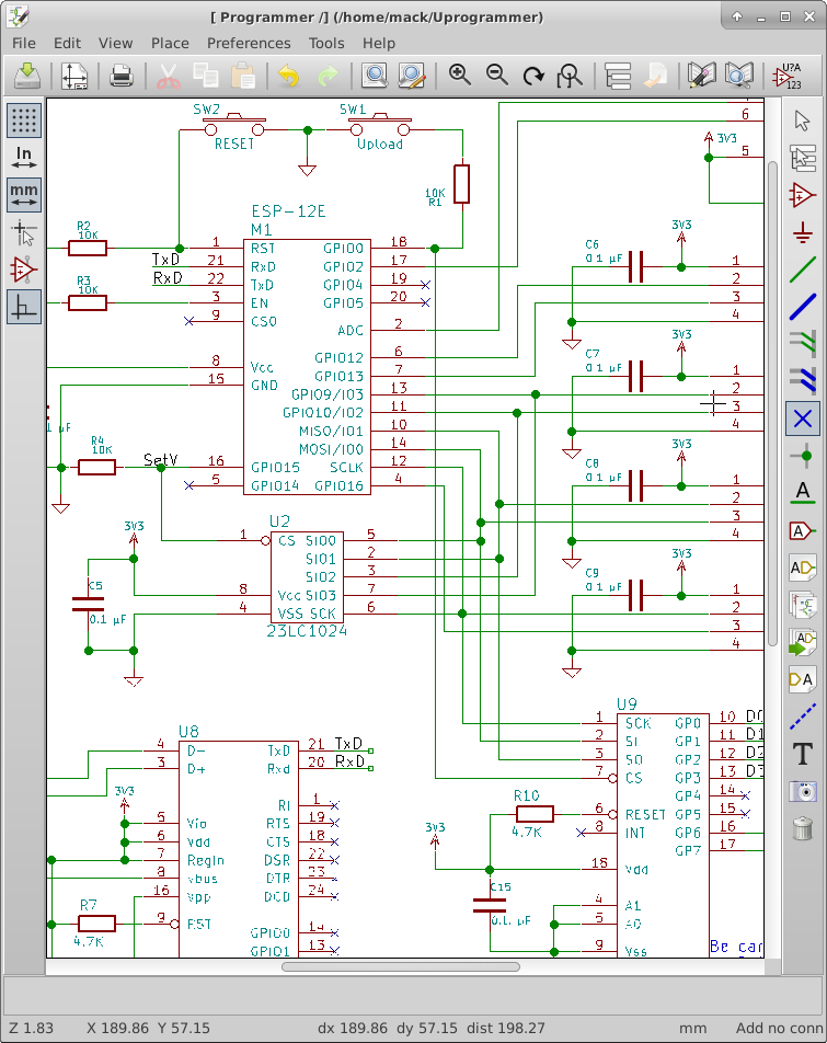
I had changed the SPI connections to correct the mistakes I had made earlier, I have gone back to verify these connections and found conflicting information. I traced the gerber image I had found to get the pinout I currently have. If it’s not correct, I will have the test pins to help me figure out the  correct pinout.

I had replace the port expander with a shift register still using the SPI to fill the register. According to the datasheet, the data shifted in will be latched on the rising edge of the RCLK pin.  If I treat RCLK as a Chip Select Pin on the SPI, a one byte write will set all of the outputs very quickly. This appears that it will work well.

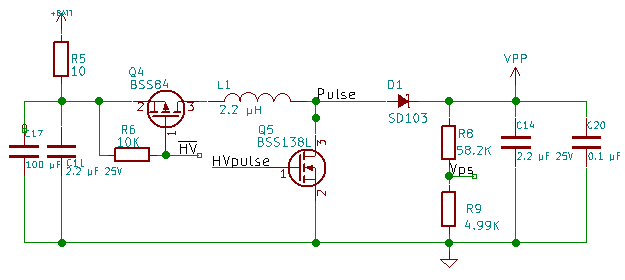
The VPP circuit changes are a big gamble. I don’t know if it will work.  I am adding a 0.1 µF capacitor to the output to reduce output noise.  I am adding a 10 Ohm resistor and a 100 µF capacitor to filter noise from getting back into the rest of the system. I need to isolate the ground of the high voltage circuit to only connect to regular GND Net at only 1 place on the layout. This will help reduce noise transfer back into the rest of the system. The design update is on GitHub, use the link in the upper right hand of the page.

V00BVPPCircuit

ADC and PWM V00D

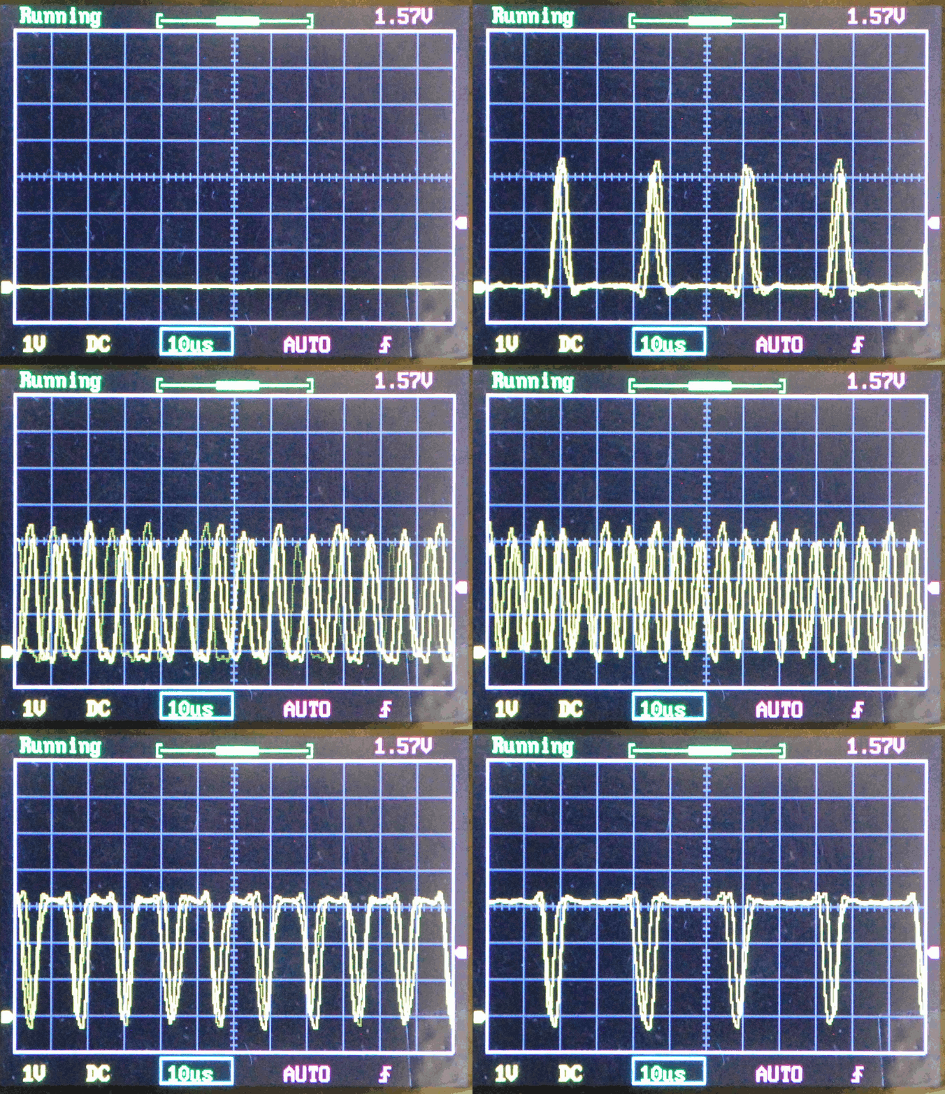
I have implemented the Reading the ADC from a keystroke (R) sent over serial. I have implemented the PWM on GPIO12.  My initial testing of the PWM has a lot of jitter and didn’t perform at the frequency I configured.  I want to set up a Hardware PWM and see how it performs.  Jitter and frequency can be important when running a switching power supply, so I want to get this right. I set GPIO2 high to select Target voltage as the input to the ADC and set a variable power supply at 0.3 volts tested it and got results around 300, then set it to 0.5 volts and got ADC results around 500 indicating it’s working as expected.

The chip doesn’t have a PWM instead it has a built in sigma-delta pulse generator.  It creates a stream of pulses to achieve the specified duty cycle by adding more pulses to fill in the middle. The chip will connect the sigma delta generator to any GPIO pin I choose.  I can use any free pin to drive the boost inductor switch. If I optimize the inductor for the width of the pulse, I should get very efficient voltage conversion.

There is no API configured for the Sigma Delta unit.  I had to write directly to the registers that set the pin connection and the Sigma Delta unit.  I had to do a lot of experimentation to understand how to set up the Sigma Delta pulse generator.  There is a piece of example code on Espressif’s forum that doesn’t work correctly, but gave me the information I needed to figure out how to configure the unit.  The example code tries to be very generic, and my code is over-simplified for testing.

SigmaDelta

External RAM

I found a big mistake.  The pinout I had used for the design has the SPI pinout wrong.  This means that the External RAM and the Port expander will not work until I fix this issue.  So, I found an online layout image that shows the flash chip as well as the pins.  I used esptool.py to request the flash ID.  The Flash ID manufacturer code is C8 and the device code is 4016.  Using Google, I found this to be the GD25Q32 made by GigaDevice.  This is a 4MByte spi/qspi flash chip.  I looked up the datasheet and found the following pinout.

1 CS#-------VDD   8
2  SO|     |Hold# 7
3 WP#|     |SCLK  6
4 VSS-------SI    5

CS#.....Active Low Chip Select
SO......Serial Data Output/ IO1 (Quad/Dual IO)
WP#.....Active Low Write Protect/IO2 (QuadIO)
SI......Serial Data Input/IO0 (Quad/DualIO)
SCLK....Serial Data Clock
Hold#...Active Low Hold/IO3 (QuadIO)
VDD/VSS.Power Connections

Looking at the ESP-12E Module layout, I found the following connections by tracing the tracks:

Flash CS# is connected to Pin 9 — No Change

Flash SO is connected to Pin 10 — No Change (MISO)

Flash IO2 is connected to Pin 11 — Requires a Change

Flash SI is connected to Pin 14 — Requires a Change (MOSI)

FLash SCLK is connected to Pin 12 — Requires a Change

Flash IO3 is connected to Pin 13 — Requires a Change

I also discovered that if I want to use the Built in SPI Chip selects, I need to use GPIO0(CS2) or GPIO15(HSPI_CS).  TxD is CS1 which is a conflict for testing so I can’t use CS1.  I found this in esp8266 datasheet.

To fix the pinout on the schematic, I went into the library editor and just changed the pin numbers. I left the pin order in place for the schematic.

For the Chip Selects, I connected the RAM CS# to GPIO15(HSPI_CS) and the port expander to GPIO0(CS2).

I have some other schematic changes to make, I am still considering changing to the CH340G USB serial bridge.  The problems that I have had have given me reason to consider not using it.  I may have a faulty chip, I will test with another one, and if the problem goes away, I will feel more confident changing to the less expensive chip.

I have added the SPI and SPI overlay library code to the project source. No functionality has changed, so I am not uploading the code to GitHub yet.

HSPIconnections

Simple Serial Firmware V00B

This week was focused on software.

I did a little research on my problem with the serial upload tool failing.  I found that I could update to a newer kernal that had been backported into the Ubuntu repository.  This kernel had the serial issues fixed.  So my vertual machine Lubuntu kernel is now version 3.19.0-30-generic.  Also, I wanted to try Windows 10 before installing the update on my wife’s computer.  I downloaded a copy from Microsoft and installed without a license key.  This is how you do a trial install.  You can go back and install a license key later.  With the new kernel and the new version of VirtualBox, programming the Esp-12E became very easy.

I have been using esptool.py on my circuit with no problems.  With the NodeMCU board that has the CH340G USB to serial chip still doesn’t work without modifying esptool.py. This is making me rethink changing to the CH340G chip because I just want it to work for someone that is developing new code.

I added a menu structure to the file simple_serial.c.  I copied some code out of uart.c that echos back what was sent.  I got that working pretty quickly.  Then I started reacting to the characters being received. I simplified the receive routine and passed the received character to the user interface function that I named simple_config_ui.  The user interface is implemented as a simple state machine that changes state based on the received character. I will use this menu structure to start testing the hardware such as writing and reading from the ram, toggling individual outputs, reading inputs, and setting the high voltage output level.

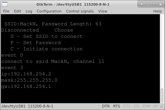
Remember the software as it currently stands is on GitHub.com.  Just click the firmware on GitHub link at the top or the right side bar on this page.  The software is functional and allows the user to connect to a WiFi access point by setting the SSID and Password through a serial port terminal.

TermnalConnected

Hello World Firmware V0A

I have finally created a “Hello World” project that works with the Espressif IOT API.

First, in the upper right hand side of this page is a link to the GitHub repository for this project firmware. The general rule for version systems is that you only commit if the code is runnable.  I hope to break the code up into small enough chunks that I won’t get a majorly broken version in the repository, however things happen. If I get stuck, I’ll commit broken code to the repository to keep it current with these blog postings.  GitHub maintains Versions, I’ll try to name each commit in a way that ties back to the current blog entry.  The current commit is the same as the post title, “Hello World Firmware V0A”

Things happened again,  I did a security update on my OS and the esptool.py firmware uploader stopped working altogether.  I did a quick search online and found that the pyserial library started failing with this update.  So I figured out how to roll back to the previous version of the OS kernel and I could get the firmware upload to work.

I copied the AT firmware project into the app directory and ran the gen_misc.sh script file to configure the libraries.  I had some problems with this and I feel I need to know more about how the makefile works.  The gen_misc.sh (gen_misc.bat for windows users) creates a file with the needed libraries for the project.  For GitHub I ended up moving the project to the folder named UProgrammer-Firmware in the same folder that the app folder was in.

I deleted the AT firmware files from the project directory, keeping the user_config.h file in the include folder. I then created a new user_main.c file that just set up the serial port to 115200 baud and sent the text “Hello World” out the serial port from the user_init() function.  This worked and I wanted to do something a little more in depth of the API functionality.  So I started a timer that calls my code called user_state() once every second.  I set up this function to send “Hello World” over the serial connection on the second call of it.  I also removed the sending “Hello World” from the user_init() function.  The function user_init() is called once during boot up of the processor.

I also added the commands to connect to my wifi network.  I verified this by using a utility to see what devices were connected to my network.  When I saw the name espressif for one of the devices, I knew it was connected.  I took one more step and added a new file called wifi.c and a new file wifi.h to the project.  To the file wifi.c, I copied a function from the API documentation that reports connection status changes to the serial connection.  I changed which UART is used so it would report back over the serial connection.  I put the prototype for the function in wifi.h.

Finally, I created a file called simple_serial.c and another file called simple_serial.h.  I plan on moving the initialization code into simple_serial.c to clean up the user_init() function.  I also plan on creating a simple text interface for configuring the connection details.

On the hardware side, I couldn’t re-solder the connector to the board because of too much damage so I cut a USB cable and used the A connector end with wires soldered to the board. I then used super glue to form a strain relief for the wires.

Boot Hello World

USB cable connection

Programming Tools

Things don’t always go as planned.  The firmware upload tools did not work.  The recommended one for Linux is a python script called esptool.py.  I hacked on it to get it working, I bypassed some error checking to get it to work.  I don’t like this but it works for now.  I have tools that proved that the USB Serial port driver was receiving the correct values but esptool.py was not.

Disabling the error checking allowed me to get pre-compiled bin files loaded onto a NodeMCU Devkit Version 0.9 and then onto my circuit.  I downloaded the AT command set firmware as well as the NodeMCU Lua firmware and tested them with ESPlorer.  With the AT command set I was able to connect to my local network, open a webserver port and see a connect attempt from a browser on my Phone.  With the Lua firmware, I was able to turn on an LED on the Devkit PCB(GPIO0) and send some interrogation commands to my circuit.

With both firmwares, the software defaulted to 9600 baud.  This worked fine for my testing.  I have not yet figured out how to get software I create into the ESP-12E. I will be starting with the IOT demo to get a “hello world” project working. A key point will be to get software of my own design working and uploaded into the circuit.  At this point it doesn’t have to have any real functionality.

I also want to figure out why esptool.py did not work, and how I can make it more robust.  If I can solve this problem, I will submit my fixes to the github repository in hopes that it will help others.

There are some things that I discovered that will change the design.  I found a USB to UART bridge that costs less than a Dollar US; the CH340G.  The programming software controls the DTR and RTS lines to automate the re-boot and flash buttons, so I can get rid of the flash pushbutton and minimize the Reset into a couple of pads I can touch with a screwdriver.  Also, on the layout, I didn’t notice that OSHpark doesn’t do plated slots.  The USB micro connector layout has slots.  OSHpark drilled single small holes in place of the slots.  I had to modify the connector to make it fit in the holes.  I will change the connector layout to round holes that will fit the shell pins of the connector to solve this issue in future runs of the PCB.  There is a flare at the end of the connector that keeps it from laying flat, I will move the flare past the edge of the PCB so the connector can lay flat against the PCB. For strength I want to add a pad under the shell that will also be soldered to the shell. I broke the connector off during my testing.

Rev0APartialBuild


Change in Design

I changed my mind, I think the programmer should be able to be reprogramed without any special tools.  This means that the Microchip processor is getting removed and replaced with a USB to serial bridge.  I have decided on the Silicon Labs CP2104 USB to serial bridge. My decision is based on cost and minimal external components. I went to several suppliers and compared 1K quantity prices.  I also confirmed that I can used the built in USB VID and PID.

I followed the example circuit in the datasheet for the CP2104 making minimal connections for a self powered device.  Since I am going to eventually have a battery that is the correct mode to wire for.

Since I no longer have the Microchip processor to control the high voltage, I connected the SET line of the AAT1230 to GPIO15 of the ESP12E.  The pulldown on GPIO15 will keep the voltage regulator disabled during a reset and I will drive it low anytime I am not using it, minimizing the current it draws from the battery.

I connected the Feedback voltage from the high voltage and the target voltage divider into an analog SPDT switch(NC7SB3157 chip) and connected the common terminal to the ADC input of the ESP-12E.  This allows me to verify what voltage the target system is at and what Vpp voltage is maintained during programming.  I ran out of IO pins on the ESP-12E, so I am added an SPI port expander(MCP23S08).  I have to give up 1 pin for chip select but I gain 8 general purpose IO pins.  So I moved the data direction control pins to the port expander and then connect GPIO5 to the CS line of the port expander. I verified the port expander could operate at 3.3V to match my operating voltage.

I connected GPIO2 to the Switch select line of the analog switch.  A high selects the VPP voltage divider, a low selects the Target voltage divider.  The voltage dividers are necessary because I could be dealing with more than the 3.3 V that the ESP-12E can handle.

None of the new devices were in the libraries.  I had to create each of the MCP23S08, the CP2104, and the NC7SB3157 in the schematic library.  I still have to connect the Vpp line to the target connector where I can leave it high impedance, set it to high Voltage, or Ground it.

USB Bridge and Vpp Port expander and Analog switch

Associating parts to pinouts

I ran the annotate schematic tool, then ERC to look for obvious mistakes.

I got a bunch of errors because I had left pins unconnected.  This is a reminder that I have to make sure these pins are set to outputs later.  I marked each unconnected pin with a no connect marker and I am down to 3 errors. I replaced the battery connector with a battery symbol.  It didn’t get rid of the error, I will have to check this connection on the netlist.

I then ran the netlist tool with default settings.

Then I ran the CvPCB module of KiCAD. I assigned footprints to the parts from the schematic.  Most of these matched.  For resistors and capacitors, I chose to use 1206 SMD for the footprints.  There is no footprint for the ESP-12E.

I found a footprint online for the module, but KiCAD would not import it. So, I created a footprint and added it to the custom library for the project.

I chose the SW_PUSH_SMALL for the two tactile switches Reset and Upload.  These are through hole footprints, I am thinking I will copy this footprint to the custom library and modify it to go surface mount.

I have only done very simple layouts.  This will be quite a learning experience for me.

CvPCB 1st

Multiplexing Pins

If you need just a few more pins on your design, one option is multiplexing.  Some chip manufacturers add multiplexing into their microcontrollers to add versatility.  Often however you have to choose between pin functions that you will use in your design.  For Instance the SPI Pins are shared with the I2C interface.  This can be hard to set up to use both.  If I have a target system that is programmed over I2C, I can use the buffers to isolate the I2c devices from the SPI bus when accessing memory.


I need to be able to pull GPIO0 low for reprogramming the ESP8266 module.  I have already assigned GPIO0 as an output to control the signal direction of the voltage buffers.  During boot it is an input to switch into boot loader mode.  I can pull it low to reprogram the module and let it float the rest of the time.  I have attached a resistor to GPIO0 and a switch to ground to pull it low when I want to reprogram the module. The resistor needs to be small enough to reliably pull the pin low during boot, but not small enough to cause damage when the pin is driving a high output.  As a rule of thumb a 10K resistor should work well.  I will have to experiment with it when I have an actual module to work with.

A 10K resistor will limit current drawn off the pin to 330µA. 3.3V / 10,000Ω = 330µA

I am almost out of pins and may have to do some more multiplexing.

I have ordered some ESP-12E modules and hope to be testing/playing with them soon.  I will probably temporarily stop working on the design and do a couple of Hello World projects.

A developer will make a simple project to test key steps of the design.  In programming this is usually an attempt to put the words “Hello World” somewhere he can see it.  This is called a “Hello World” project. For hardware, this can be as simple as flashing a LED. In this design flashing an LED would prove I could reprogram the device, and have a basic understanding of the build toolchain.