The purpose of the schematic design is to organize the design elements in a way that is clear and easy to follow. The schematic is used to show the electrical connections between components in a circuit.
I opened the schematic.
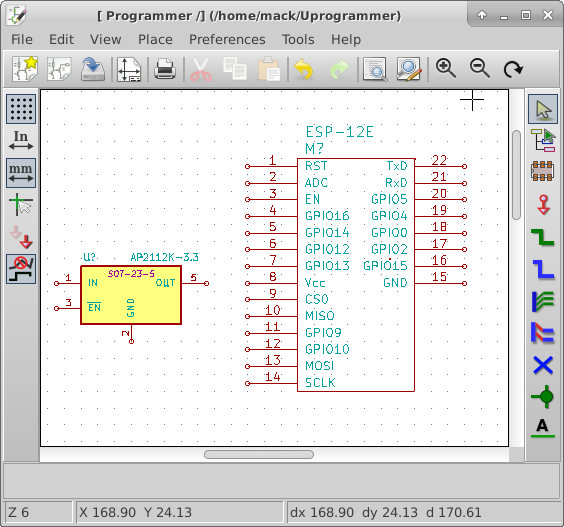
I placed the ESP-12A and noted the power connections Vcc and GND. This device requires 3.3 volts operational voltage so I will need a voltage regulator to supply the radio. While looking for more data concerning the ESP -12E I found a better pin layout and description on ESP8266.com. On line I have found the part draws 300 mA at peak.
Searching on Digikey, I found a regulator AZ1117CH-3.3 under US $0.09 each in quantities of 4000. It looked like a very good fit until I looked at dropout voltage. With a 3.7 V lithium battery for the supply, a dropout voltage greater than 0.4V is too much. Typical dropout voltage for this part is 1.2V.
Note: Dropout voltage is the minimum extra voltage above regulated to maintain regulation. I 3.3V regulator with a 0.5V dropout voltage requires an input voltage of 3.3+0.5 = 3.8V to still be able to regulate to 3.3 Volts.
So I look again, I have used and like the AP7333-33 voltage regulator. It’s maximum current is 300 mA. that doesn’t leave any margin. I keep looking. The next part I find from Digikey is the AP2112K-3.3. It can run at up to 600mA leaving plenty of margin, with a dropout voltage of 0.25 V. The price is under US$0.11 each in quantities of 3000.
I add that to my library and to the schematic. I found a similar SOT23-5 pin part exported it. I then imported it in the the programmer library and edited the part name to match the ordering number.