I have three things left to test before I re-layout the board. The high voltage generation and the io channels, and the ADC/Analog Switch. Since I have to control an IO pin to change the voltage output of the boost regulator, I will effectively be testing both together. I Soldered the inductor, diode, and feedback resistors on to the PCB. I will do the analog testing next week.
I start by adding a new command to the simple serial menu. Since we are changing voltage I think tapping V is a good choice to increment the Voltage value. First thing to do is set GPIO15 as an output and drive it low(Reset the Voltage Boost regulator). When the system displays the menu, then I set GPIO15 to a high value. This will allows me to check the status of the pin with a volt meter. I expect it to be near zero V for about 1 second then about 3.3Vafter that until I can implement the next step. I confirmed these values proving the gpio capabilities are working as expected. Now I should also be seeing about 6V at the test point on the output of the boost regulator. I did not see any voltage at the test point.
I need to figure out what is wrong with the voltage regulator, first, I am going back to the datasheet to verify I know how to set the voltage level. I inspected really closely and found that pin 12 of U7 did not take solder when I added the chip to the board. With no connection on pin 12, no voltage could get to the inductor. To fix this, I overflowed pins 10, 11, and 12, then used solder wick to remove the excess. This still took several tries. With the chip soldered correctly, I am now getting 7.7 volts about 1 second after I connect power to the board.
I added the V command to the parser to step this voltage. I managed to damage the boost regulator during testing. I am looking remove this regulator and implement one using the PWM. This choice will reduce the cost as well as simplify the PCB design.
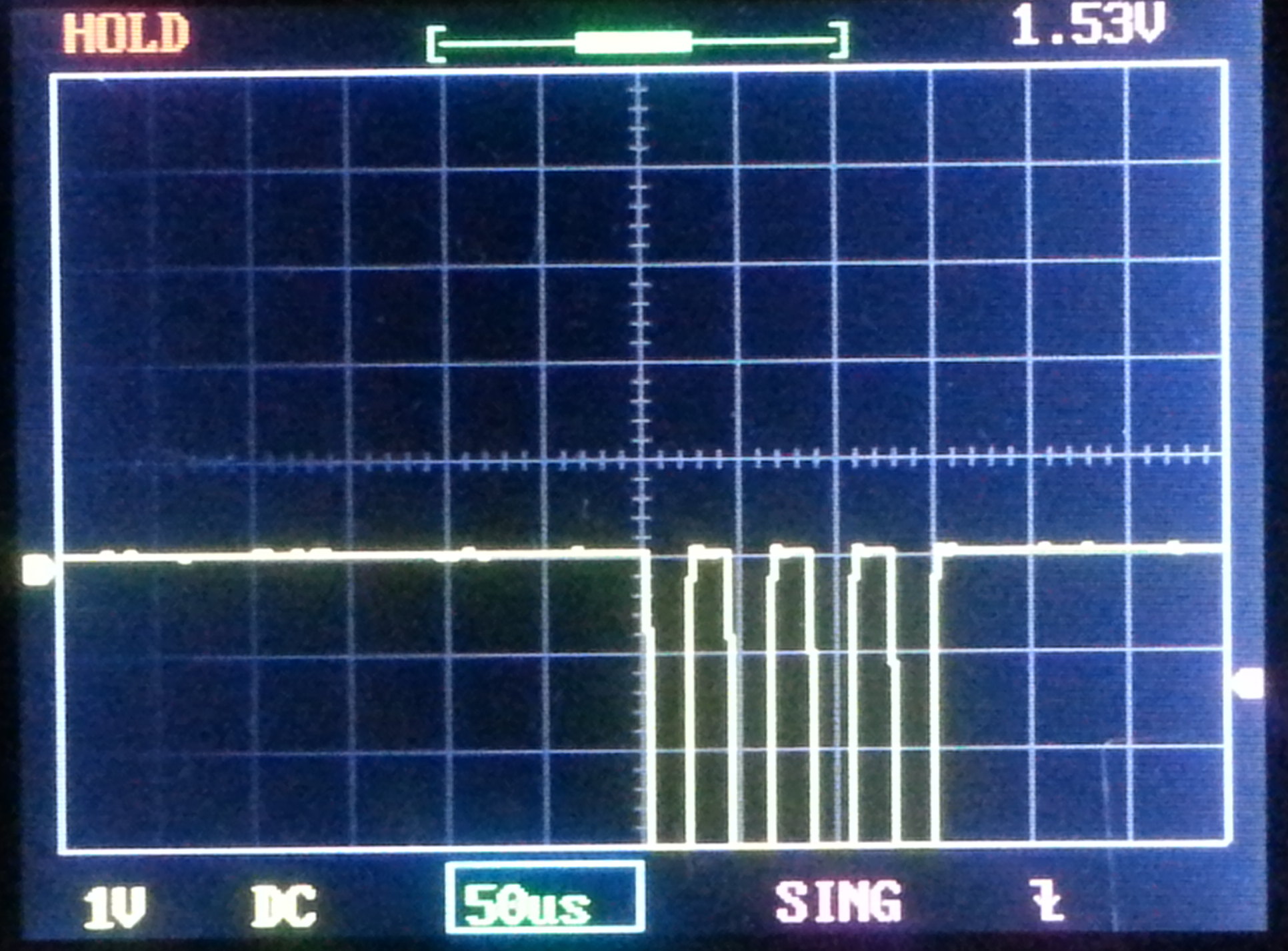
Since I damaged the regulator, I decided to test the GPIO functions on an IO that wasn’t connected to anything at the moment. I chose GPIO12. I added a command in the simple serial menu that sends a stream of 4 low pulses approximately 20 microseconds wide and separated by 20 microseconds. I chose 20 and 20 because I have a kit oscilloscope that has a 200KHz bandwidth that I wanted to test with.
I want to test PWM capability next week as well. I have updated the code on GitHub.