Troubleshooting

I started out this week by hooking the SPI RAM to the logic analyzer. Then I hooked up the USB cable and it was stuck in a reboot cycle. I set the flash speed back to 20. Still stuck in reboot cycle. I disconnected the logic analyzer still in reboot loop.  I commented out the initSpiRam function in the startup code still stuck in reboot loop. This leads me to believe I have a power supply problem.

If it’s a power problem, adding large (100 μF) and small (0.01 μF) capacitors around the ESP-12E would solve the problem.  The 100 μF capacitor will act as an energy reservoir. The small capacitor will act as a noise filter. I piggy backed both a 100 μF and  a 0.01 μF capacitor on top of C4 the decoupling capacitor for the ESP-12E module. This didn’t solve the problem.  Next I suspected the SPI RAM was the problem.

I probed CS0 along with the SPI RAM CS line and they were in perfect phase.  This means that Q6 is not inverting the signal. This results with U2 on the SPI bus while the flash is being accessed.  That would definitely get it stuck in a reboot loop.  After feeling stumped for a while, I replaced Q6. It booted normally again. I uncommented the initSpiRam function and it started rebooting again. I tried with and without initSpiRam being called and it would consistently reboot when initSpiRam was called.

With initSpiRam uncommented, I went into the function and started commenting out lines to see what was causing the reboot.  It appears that ENABLE_SPI_DEV_CS() is causing the reboots. I moved it to after spi_master_init to see if that would work. spi_master_init(HSPI) by itself works. Next I tried adding overlap mode. It appears that overlap has to be after master init.  The SPI driver files and headers don’t have any way to read back data while in SPI master mode.

I decided to do a very simple test. I would do a SPI Master Write without overlap mode turned on. One write of one byte immediately after boot so it would be easy to catch on the logic analyzer.  The HSPI pins are:

GPIO14: CLK  Pin 5
GPIO12: MISO Pin 6
GPIO13: MOSI Pin 7
GPIO15: !CS  Pin 16

Chip select is the same pin I am already using, the rest are unconnected. I put a jumper across Q6 to always disable U2 by pulling CS (pin 1) high. I also soldered test points to each pin so I could easily attach the logic analyzer. With the jumper across Q6 I couldn’t even program the board!  This doesn’t make sense, I’ll have to come back to that.  I think I have some mis-wiring. I removed U2 from the board, and this allowed me to reprogram the PCB.

It now boots but doesn’t give me a menu. It appears to hang on the spi_mast_byte_write() call.

This is not a big deal, I haven’t set the SPI port.

All that time spent fighting this problem, and it turned out to be a solder bridge between R27 and a PCB trace from FLASH CS0.  I cleaned up this bridge and it started working reliably.

Finally I tested the basic HSPI write function. It didn’t work. but code is running without freezing or rebooting.  So I added a call to spi_master_init() still not working, no data on lines.  Looking in spi.c, I saw that spi_master_init() doesn’t assign pins to the HSPI port.  I added the lines below to user_init(). HSPI_PIN is defined as 2.

PIN_FUNC_SELECT(PERIPHS_IO_MUX_MTMS_U,HSPI_PIN); // GPIO14
PIN_FUNC_SELECT(PERIPHS_IO_MUX_MTDI_U,HSPI_PIN); // GPIO12
PIN_FUNC_SELECT(PERIPHS_IO_MUX_MTCK_U,HSPI_PIN);// GPIO13
PIN_FUNC_SELECT(PERIPHS_IO_MUX_MTDO_U,HSPI_PIN);// GPIO15

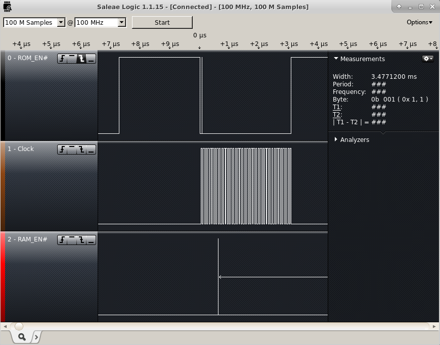
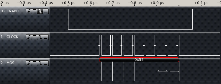
And I saw a byte on the logic analyzer. Yeah! progress.

SPI Byte outThe data speed is at 20MHz. I tried two writes in a row and got a chip select active for each write, and inactive in between. I need to figure out how to change this behavior, the SPI RAM commands always follow the falling(going active) edge of chip select. To write data to the RAM, I have to send more than one byte while chip select is active.

How do you do troubleshooting? Have you gotten HSPI Working on the ESP-12E? Does anyone know if there are different pinouts for the ESP-12E? Something I saw suggested to me that I still have the SPI RAM connected wrong again.

New PCBs

The PCBs arrived this week.  I really like the way my Logo came out.  20160415BarePCB

I do want to make an adjustment, make the arrows larger, they didn’t even show up on the silkscreen.

PCBLogo

To start testing, I put a jumper in bypassing the lithium cell charger. I then installed the ESP-12E, the SPI RAM, The Crystal, the USB Serial Bridge, the voltage regulator, and the USB connector. Just enough to power up, load a program and test the basics.

20160415assembledPCB

First test was to  connect to PC and run ESPlorer– it worked.

I got a message:


AT-based firmware detected.
AT+GMR
AT version:0.40.0.0(Aug 8 2015 14:45:58)
SDK version:1.3.0
Ai-Thinker Technology Co.,Ltd.
Build:1.3.0.2 Sep 11 2015 11:48:04

I then tried to install my test version of the software and it wouldn’t install.  I went back to ESPlorer and started playing with the DTR and RTS to see what would happen. It turns out I got DTR and RTS backwards. So I cut the traces and added a couple of jumpers. This is the kind of mistake I was hoping to catch in the design review.

It programmed great with the wires swapped. My code crashed, back to a “Hello World” version.

Turns out the internal memory chip installed on the ESP-12E does not run at the settings I had specified with esptool.py.  I found this out by setting it to 20MHz DIO mode which started working. I then switched it to QIO mode to see what happened. QIO worked, next I tried running at 40 MHz. That worked.

../esptool/esptool.py --port /dev/ttyUSB0 --baud 230400 write_flash -ff 40m -fm qio -fs 32m 0x00000 ../bin/eagle.flash.bin 0x40000 ../bin/eagle.irom0text.bin

I enabled HSPI Overlap mode by adding spiRamInit() to the end user_init(). Ran without crashing. When I started building for use, I discovered no SPI Master Read available.  I saw something that looked correct for slave read, so I borrowed a line from it and did a write followed by that line– it built. I uploaded the code, and it ran, still no testing of the SPI Ram.

I added the function calls to write “Hello World” to the SPI RAM. and read back and put out to the console. and I got garbage back to the console.  Not a surprise. Debugging with a logic analyzer next week.

Have you written code for the ESP8266. Have you worked with SPI before? I would love to Hear from you.


SPI RAM

I am anticipating the new PCBs coming in soon, (I have a tracking number but it doesn’t show up with Hong Kong Post or USPS). In light of this, I decided to do a little research on the SPI RAM so that when it gets here, I can quickly write code to test the functionality of the design.  The SPI RAM I have chosen is a 23LC1024.  A common manufacturer of this chip is MicroChip, I downloaded their datasheet for this chip and started looking at the process to write to and read from the RAM.

Notes for writing to SPI RAM:

Maximum 20 Mhz Clock for all data transfers (might cause me to slow down the FLASH)

Write speed only limited by clock speed.

Write command(0x02) followed by 24bit address followed by data

Page Mode 32bytes before sending a new address

Sequential mode can fill the whole RAM

Write is terminated by CS going inactive(HIGH)

Notes for reading from RAM

Same maximum clock speed.

read only limited by clock speed.

Read command(0x03) followed by 24bit address start receiving/clocking data from RAM

Three modes of operation, Byte, Page, and Sequential.

Byte mode only allows reading/writing one byte before having to resend an address.

Page mode all data is accessed in pages of thirty two bytes. Not very useful for this project.

Sequential mode allows access to all of RAM as one big block that I can start accessing from any point. I need to set the mode register bits 7 and 6 to 01.

I am going to start in standard SPI mode, Make sure it is working then adjust the code to start taking advantage of the SQI interface.

SPI RAM testing (Firmware V00F)

The SPI RAM was still unproven.  I want to test it before I do a new layout.  I checked the SPI lines with a Saleae Logic16 which unfortunately can only sample 3 lines at 100MHz  I was concerned that the SPI RAM would be on the SPI bus at the same time as the FLASH.  This could occur anytime the CS0 and the HSPI CS were low at the same time while the processor was writing or reading from the flash. So I connected to the two chip select lines and the SPI clock line. I triggered capturing off of the first falling edge of CS0.

SPI Enables

I configured GPIO15 to HSPICS at the beginning of user_init and it appeared to not make any difference.  I then changed it to a digital pin and set it high and still didn’t appear to make a difference. So I guessed something I was initializing was causing it to change back to the mode it had been in before.  I set the Pin to a Digital output and set it high at the end of user_init, and it worked.  Since that worked, I tried changing the last step in user_init to set up the SPI overlap configuration. This also works.  It looks like that for about 300 ms there is bus contention between the SPI RAM and the FLASH memories.  This has got to be solved before I go to a new layout.

What I need is to keep the SPI RAM CS line high anytime the FLASH CS is low but follow GPIO15 the rest of the time. It’s helpful to look at in a truth table.

GPIO9  | GPIO15 | SPI RAM
 CS0   | HSPICS |    CS
--------------------------
   0   |    0   |    1
   0   |    1   |    1
   1   |    0   |    0
   1   |    1   |    1

There is only one zero in the table, this means it can be represented as an or gate. If I invert CS0 and or the signals together I would get the results I want. I figured out a circuit that would work that just adds a transistor, a diode, and a couple resistors. A PNP transistor to pull the line up when CS0 is low and a diode to block the current when GPIO15 is driven low at the same time that the RAM CS is pulled high.  There will have to be a pulldown resistor to make sure the CS will go low when it needs to.

I have pushed these minor firmware changes to github.

SPI Overlap