Successful Test

Side Project:

I got the parts to build the OLED breakout PCB this week. I got them assembled and connected to my test STM32 Arduino device. Unfortunately, I didn’t get anything to show up on the display.  I did measure the 13.8 volts on the high voltage part of the circuit. (I wasn’t sure if the inductor I chose for this voltage could handle the current. I am still not sure)

The STM board got hot quickly when trying to drive the OLED. This leads me to believe that the OLED is drawing too much current.  I expect this display to work as well as the test display I have been using. It should draw about the same amount of current. My first guess is I have a solder bridge somewhere on the PCB.

Research:

I created a C project with multiple files and it worked without any problems. So I did a little  research and found that when I add C into a C++ project I need to tell the compiler which functions are written in C.  I found that I can wrap the #include in an extern “C”{} declaration.

Still Looking for a Fail:

Continue reading

Unit Testing

TDD/Unit Testing:

I searched some for TDD tutorials this week. and found a few. Unfortunately, I found tutorials with no or very little “hands on” practice.  So I am still looking for good tutorials.  When I find some, I will post links on this blog.

What I have gleaned from the tutorials so far is that when building your code, you replace your main file with your testing file(s) so that the tests can call each of the functions/methods individually with known values and should get back predictable results.

Embedded Units Testing:

For embedded systems unit testing, my code will be compiled to run natively on the development machine rather than being compiled for the target processor.  This means a different tool chain for test build than for production or debug builds.

Note: Tool Chain is the set of tools that are used to create machine runnable code from your source files.

Any API call or peripheral device needs to have mock code that can be run as part of the tests.

Note: Mock Code is software that represents things that are not on your testing machine, or would hinder testing.

“Hello World”:

Continue reading

Layout check … continued

With the new check plots I made last week, I checked the layout net by net like I did back in Sept 5, 2015. I am still uncertain about the pinout of the ESP-12F modules. To test it, I removed the ESP-12E installed on the board I am currently using, and replaced it with a new ESP-12F.  I had to be careful that the jumper wires all got back to where they were before removing the module.

The new module programmed first try but didn’t boot correctly.  I had forgot to upload default values, the flash comes programmed for a different memory layout.  Once I installed the default settings, it booted up correctly.  I had removed the test for HSPI/SPI RAM, so I went back into the code and re-enabled the Hello World ram test.

I went into serialInit() and changed the line DISPLAY_MENU(); to DISPLAY_MENU_W_SPI(); Re-compiled and tested.  Unfortunately the result was not “Hello World”. When I cleaned up the code, I made the write to SPI RAM easier, but I need to initialize the hspi.  I started connecting my mixed signal oscope to analyze what was happening on the SPI bus.  And… I found a loose jumper wire.  The one that connects the chip select between the ESP-12F and the SPI RAM. Once this was connected, the extra stuff I had put into the software became unnecessary.  I deleted the extra code and it works just fine.  The firmware is back to where it was before I started testing. There are no changes to upload.

This means that the circuit is tested and the current layout is ready to send to fabrication.  I zipped up the gerber files. Then checked pricing with PCBway, DFRobot, and Seeed Studio.  With shipping PCBway came in a little less at US $19.  With PCBway, I have to wait for a design review before they will give me a final price and allow me to pay for it. Usually this is pretty quick but depends on the day it is submitted.

Have you bought boards from Chinese manufacturers? How quickly did you get them?

Hantek MSO5202 Mixed Signal Oscilloscope review

mso5202d(Picture taken from Aliexpress.com)

Features:
This scope has 2 analog channels and 16 digital channels With Bandwidth up to 200 MHz.
1 Million sample points for the analog channels.
512K sample points for the Logic Analyzer channels
7 inch 800×400 color LCD display
USB Host for flash drives
USB client for PC control

Pros:
Capture 16 channels digital and 2 channels Analog simultaneously.
Export captured data to CSV file (useful for analysis)
Linux based (hackable!)
Familiar knob/face layout
Bright clear display

Cons:
No protocol analysis built in. No way to add protocol analysis.
No Linux PC support
Occasionally crashes
D0 is only digital trigger line

My experience with this scope:

The Purchase:
I bought the scope off of Aliexpress.com.  I knew I wanted at least 100MHz Bandwidth. I also didn’t have a lot to spend.   There wasn’t a big cost savings to go to the 100 MHz scope, so I decided to go ahead and get the 200 MHz Version.  Since I have bought the scope, I have seen information on how to hack the 60 or 70 MHz models to get the full 200 MHz performance. Assuming the scope lives up to their specs, I am happy to pay for the Higher bandwidth.  This scope is still a bargain with a price less than $500 US.  The seller shipped it to me for free with DHL shipping. The scope was delivered within 7 days.

Unboxing:
The scope came in the manufacturers box inside of another box it just fit inside.  I cut the tape on the outer box and opened it to see a handle on top of the manufacturers box.  I started to lift by that handle and the bottom of the manufacturers box fell out.  I had only lifted it a few inches so the bubble plastic protecting the scope protected it from damage.

First use:
I connected the power cord and nothing else. Turned on the power and it booted up quickly (less than 10 seconds). I then dug out the probes and hooked them up. The probes came with color rings to help identify which channel I was using.  Both probes came with red rings on both ends of the probe.  I looked at the scope and saw that the color for channel 1 is yellow and the color for channel 2 is blue.  I grabbed one of the probes and switched the colored rings to yellow and connected it to channel 1.  I repeated that process with blue rings for channel 2.  I connected the probes to the calibration tang on the front of the scope and did a quick adjustment of each probe.  The knobs have a good feel to them and the waveforms change the way I anticipated for each turn.  This made this scope feel very familiar.  All of this was done without reading the manual. So far so good!

Tinkering:
I have a circuit that the LCD got damaged on and I wanted to see how the Logic Analyzer worked.  The LCD is controlled by SPI. I hooked up the data lines, figured out how to trigger off of D0 and it kind of worked.  It wasn’t real clear how to get to the Logic Analyzer to begin with. I found it with playing.  Then I figured the chip select line of the LCD would be a good choice to trigger off of.  There is a short glitch just after power up that meant the scope triggered way too early.  I was disappointed that I couldn’t change the trigger to a different digital channel, I had to move the connections around instead. To make the connections to the LCD, I had to solder several 30 gauge wires to the data lines I was interested in. These wires are fragile so changing the connections to them was difficult.  The scoped locked up or did weird things while I was tinkering.

Data Capture:
I was also disappointed that there was no simple data analysis for the Logic Analyzer system.  I captured a chunk of the LCD SPI data and saved it as CSV file to a flash drive.  I put the flash drive into my computer and opened the CSV file with LibreOffice Calc.  With some complex cell calculations I was able to get Calc to show me the data that was sent for each time chip select was active. The good news is it showed me the circuit wasn’t damaged and a replacement LCD should fix the device.(The scope served it’s purpose)

Overall:
I found this scope to be very intuitive to use for analog signals.  The Logic Analyzer function is very useful but is not very intuitive and is missing some features.  If I had this when I was testing the SPI on the Uprogrammer board, I would have found my problems much quicker.  I watched a few of the hack videos on YouTube. They connect a USB to Serial bridge to the system and issue a few Linux commands. Linux is a great place to start hacking. On the back is a punch out with a Networking symbol next to it.  If it turns out that there is a chip that supports ethernet on the board, I would like to install the ethernet jack and see what happens.  From the hack videos, I can see there is a place on the PCB for the ethernet Jack.

My Opinion:
This an excellent scope for the price.  I have seen online videos that indicate problems when approaching the higher bandwidth limits of the scope.  I don’t believe these problems will affect me.  If you need high precision in near 200 MHz, I would suggest looking for a better scope.  Otherwise this will make a fine tool on your bench.  Firmware is still being developed for this scope, so I expect it to get better over time with updates. Since it is Linux based I also expect the community to hack it for better features than just a bandwidth upgrade.

Have you used one of these scopes?  Have you worked with one near 200 MHz?  What is your feelings about the lack of digital features? How about the occasional lock up?

Voltage Boost testing

I have a very stable version of the Sigma Delta(ΣΔ) firmware to test with.  I decided to use it to test the Voltage boost circuit.  I started by populating the PCB with the voltage boost components.  Definition: Populate a PCB means installing the components onto a board; this includes but isn’t limited to soldering.

PCBVboost  PCBVboostPop 

Once Installed, I started modifying the code for a simple test. The first test is a sanity check.  I disabled all functions other than sending an incrementing number out the serial port every 5 seconds. And then I ran into another problem.  I had upgraded my install of Ubuntu studio to 16.04 earlier this week and now USB wasn’t working in the virtual machine.  After a few hours of fiddling, I got it working and finally built and uploaded the test code.  The terminal started counting as expected.

Next I turned on the ΣΔ and set the duty to 16. I figured out the prescaler with the following math.  An inductor will reach approximately 2/3 saturation current after a given amount of time calculated by inductance divided by resistance.  I am using a 2 μHenry inductor with an internal resistance of 0.25 Ohms. 2×10^-6 /.25 = 8×10^-6 or 8 μsesonds.  So the most efficient use of the inductor will be between 4 and 8 microseconds. One cycle (pulse width) at 80 MHz is 12.5 nanoseconds. This results in a prescaler of 640 for an 8 microsecond pulse width. If I choose a prescaler of 255, I end up with a pulse width of 3.2 microseconds.  This is a simplified calculation and I hope it will get me close enough.  The PCB resistance, capacitors, and R5 all contribute in varying degrees. I also set GPIO16 as an output and drove it low to enable the voltage booster.  And the code ran as I was hoping for.  I measured the Vpp voltage at 5.93 Volts which is slightly above the 5 volts being supplied by the USB. Yeah! small victory.

The next firmware modification turns on the Sigma Delta and set the duty cycle to 128 (50%) .  I measured 2.75 Volts. So next I read from the ADC each time I sent to the terminal.  The value I read back was 137.  Then I enabled changing the duty with each update. and the values changed with each step.  Very good. Next I did a little math on the data. The ADC reads 1/1024 V/step.  So when I got the reading of 137, that means (137/1024)*20 = 2.675 V.

I get a small error but within 5% reading a meter verses calculated.  I fixed this by changing the 20 to 21.  I got the error because of a 5% error in the calculation of the voltage divider.  I had known about this error, but was ignoring it.  Now it is fixed.  I then started to play with the prescaler to see if i could make it work better.  The 100 Ohm resistor is having more affect on the circuit than I had anticipated.  With a prescaler of 128, Vpp rises to 8V.  At 64 Vpp rises to 11.6 V. At 32 Vpp Rises to 11.6 V again. At 16 the Vpp Rises to 11.6 again.  This suggests the design is limiting the max voltage. I need to check the reverse breakdown voltage on the diode and FET.  I would like to see better control between the steps.  With a prescaler of 0 it Vpp peaked at 12.1 V.  It took more steps to get there, and the steps weren’t linear.  It still needs tuning, maybe a different inductor.

This was fun playing with the Voltage boost circuit.  I actually got it to work fairly well.  This is the first switching boost circuit I have designed from scratch. Of course, I have had a few bumps along the way.  I have uploaded the test code to GitHub.

Have you designed a circuit that was out of you normal area of expertise? I would love to hear about your experience.

Sigma Delta Testing V00A

I have been fighting using the Sigma Delta(ΣΔ) for a few weeks now and all of my research so far has not been fruitful.  So, My intention this week is to implement a very basic ΣΔ operation that will change the prescaler for the whole range of possibilities 0 – 255.

The hardware watchdog timer triggers after about 6 seconds without a WDT reset. I have decided I want the sigma delta prescaler to step from 0 to 255 every 5 seconds.  I will put each step of the prescaler out to the serial port using system calls.

I will put all the code in the user_main.c file so that I, and anyone else that looks at my code can see all that is going on.  I extracted a new set of SDK files into a new folder called SigmaDelta.  I then created a new Eclipse project file in this new folder.    I struggled with creating the project in Eclipse.  I finally got it set up the way I wanted.  In the past setting up a project in Eclipse has always been easier, but this time it just didn’t work well for me.

I copied my shell scripts(that is batch files for windows users) that I use to automate building and testing from the UProgrammer folder. Next, I removed the references to AT_CUSTOM_UPGRADE in user_main.c and user_config.h.  I then performed a sanity check by putting one line of code to send “Hello World” out the serial connection and tried to build.  It failed because I forgot a semicolon.  I fixed that and got a new message saying code will not fit in irom0_0_seg.  I need to update the linker  file.  I copied the one from the UProgrammer folder.  Built again and it compiled. Next I uploaded it to see if it still works.  It doesn’t seem to work.  The baud rate is set to 115200, but I am getting a little bit of garbled text after boot completes.  I decided to try putting a small delay(5 ms) in before printing the “hello World”. This also didn’t work.

I need to implement a timer and looked at the sntp example in the API guide.  I set the timer to repeat every 5 seconds. Unfortunately it seems to just hang. I had a similar problem when I moved to this version of the API, I removed the uart_init line and I started getting regular data coming across the serial line. Still garbled, but happening every 5 seconds.  So I looked at uart_init from the uart.c. I found and copied the call that actually sets the baud rate.  I used this to modify the baud rate for UART0 and I started getting Hello World every 5 seconds.  Next step, turn on the Sigma Delta and start incrementing the prescaler.

I created the variables prescaler and duty and set them to 0. Then I went back to my old code and grabbed a copy of the set prescaler code.  I put the code in to set the prescaler, increment it, and print out the value every the timer event is called. I compiled, uploaded it and I saw numbers increasing across the serial terminal.  Then I waited for it to get to 100.  It continued to count.  I let it continue all the way up to 255 and then changed the wifi mode to STATION_MODE like the UProgrammer firmware. Next, I modified the code to turn on the output(GPIO4) and change the duty cycle.

Still working. Connected to wifi and tested again. Still working.  I explicitly set GPIO4 as an output set to 1 and tried again. Still working I turned on HSPI overlap mode and tried again. It started crashing and rebooting.  It looks like somehow the HSPI is conflicting with the SigmaDelta generator.

I commented out the code to set up GPIO4, and the code to connect to the wifi access point and it crashes. I changed the duty back to 0 and it doesn’t crash anymore. Next I checked the Pin assignment worksheet to see what else is connected to GPIO4 and I didn’t find anything interesting.

It looks like I have to do an HSPI overlap deinit immediately after getting data out of the RAM.  This could be a problem because I want to be generating Vpp while transferring data into the processor.  This could limit my options.  If my code is small, I can generate Vpp. If it’s large, I may have to program in blocks.

I do have the capabilities to assemble and test the voltage booster now.  I will go back into the UProgrammer Firmware code and deinit the HSPI overlap and see what happens.

I have put this week’s test code on GitHub here. How do you find problem code?

Sigma Delta still causes reboots Firmware Version 00E

I was hoping but not expecting the SDK Update to fix the Sigma Delta problem.  So first thing I did this week was to test.  Same failure as before.  I had two Ideas this week that might be an answer to the problem.  On another project, I was using the Arduino IDE to develop a little weather station project.  In it, I was using old code that set certain pins as output.  Those pins were/are tied to the SPI bus and was causing it to reboot.  Maybe, there is a pin set to have Sigma Delta(ΣΔ) output that is also tied to a critical pin.  My second thought is that if the ΣΔ is causing interrupts, I should disable them.

A good practice for microcontroller programming is to always set up all I/Os immediately after a reset.  I have gotten sloppy and haven’t done that with this project. If a pin is connected to the ΣΔ that shouldn’t be, this will fix that.
I started by writing down what each pin will do in the design. I referred to the schematic for each pin.

Pin 18 GPIO0 -- Output -- controls analog switch
Pin 22 GPIO1 -- Output -- TxD0
Pin 17 GPIO2 -- Output -- sets VPP output high
Pin 21 GPIO3 -- Input -- RxD0
Pin 19 GPIO4 -- Output -- ΣΔ pulse stream to generate Vpp
Pin 20 GPIO5 -- Output -- Sets Vpp output low
Pin 14 GPIO6 -- Output -- SCLK (SPI and HSPI overlap) (need to verify Pin number for ESP12F)
Pin 10 GPIO7 -- BiDir -- MISO (SPI and HSPI overlap) (need to verify Pin number for ESP12F)
Pin 13 GPIO8 -- BiDir -- MOSI (SPI and HSPI overlap) (need to verify Pin number for ESP12F)
Pin 11 GPIO9 -- BiDir -- QIO2 (SPI and HSPI overlap) (need to verify Pin number for ESP12F)
Pin 12 GPIO10 -- BiDir -- QIO3 (SPI and HSPI overlap) (need to verify Pin number for ESP12F)
Pin 9 GPIO11 -- Output -- CS0 (SPI) (need to verify Pin number for ESP12F)
GPIO12 -- BiDir  -- Data to target device
GPIO13 -- BiDir  -- Data to target device
GPIO14 -- BiDir  -- Data to target device
GPIO15 -- Output -- Chip Select for HSPI
GPIO16 -- Output -- Disables Vpp generation

I went into the user_init() function and removed all the commented out code leaving an example of the PIN_FUNC_SELECT() macro. I then set GPIO_PIN0 – 15 registers to 0 which disables interrupts and disconnects the ΣΔ output.  I compiled the code and uploaded it and it crashed.  To find the new problem I caused, I commented out all the new code except setting the GPIO registers to 0. I rebuilt and uploaded the code and … a continuous stream of reboots.  I commented out setting the GPIO registers to 0 then put the PIN_FUNC_SELECT() back in. And … reboots slowly.

I removed the function selects that should be controlled by the API anyhow(GPIO6-11). And … I found a typo on the GPIO6 function select. I fixed the typo, rebuilt, uploaded and it ran at least as well as last week.  I then started testing to see if it fixed the ΣΔ issue. The reset problem still exists.

Next I set a subset of the GPIO registers to a value of 0  I decided to go with the first 8 to see what would happen. Same failure, a stream of reboots. Then I noticed I wasn’t writing to the correct register locations.   I fixed this and then recompiled, uploaded, and code is running, but ΣΔ is still causing a reboot if i set the prescaler to greater than 99.

Next I started looking at the ΣΔ interrupt structure.  Unfortunately it has very little documentation that I have found so far.  I used google to search for articles pertaining to the use of the Sigma Delta and found very little.  My next step is to do a little experimentation. I decided to disable the ΣΔ while changing the prescaler.  I got the same results.  It’s time to make a Hello World program for a sanity check. It would be the minimum to set up and test functionality of the ΣΔ on GPIO4.  If it works correctly, then I have to take a deeper look at my code, if it doesn’t, I’ll have something to post to Espressif’s forum for help.

Have you had similar problems with a chip you have never used before?  I have uploaded the current code to GitHub. Use the link at the top of the right hand column to get the download.

Update to SDK 1.5.4 Firmware V00J

Since I don’t seem to be making any progress on the Sigma Delta output, I decided to update my copy of Espressif’s API. I went to bbs.espressif.com and clicked on the SDKs thread under the heading DOWNLOADS. In the list i looked for the most recent Non OS SDK release.  I saw that ESP8266_NONOS_SDK_V1.5.4_16_05_20 is the most recent release. It’s file name indicates a release date of May 20th 2016.  I downloaded the zip file and extracted the contents.

To Make moving forward a little easier, I renamed the SDK folder to UProgrammer.  This will help me maintain paths the next time I move to a new SDK Version.  Each time I update to a new SDK, I will Rename the OLD SDK folder to indicate it’s version number, and rename the new SDK folder to UProgrammer.  To maintain compatibility with Github’s folder naming, I will continue to keep the UProgrammer-Firmware folder name for the project files.  This folder will be sitting in the SDK folder I just renamed to UProgrammer.  I then created an empty text file with the name of the SDK file to mark the version I am working in.  Then I copied the hidden file .metadata from the old SDK folder into the new (UProgrammer) SDK folder.

I opened eclipse and pointed the workspace to the UProgrammer folder and it loaded the files as if I hadn’t changed anything. Then I made edited the comment block at the top of the file to indicate I had moved to NONOS SDK V1.5.4.  I saved the file and then checked the file in the new directory structure for the changes. It has the change I had just made.  To make sure there wasn’t something weird going on, I also checked the file in the old directory structure. It was unchanged.  I had planned on dealing with more problems just in case they happened.

I compiled the code to see if anything broke moving to the new SDK.  Things definitely broke. First the files all compiled but linking failed.  The first error message was:

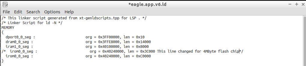
section `.irom0.text' will not fit in region `irom0_0_seg'

This reminded me that I modified the linker file eagle.app.v6.ld to allow for more room for the code space in a 4MByte flash chip.  I made the modification to the new file and saved it.

Modified linker file

I tried compiling again.  Again it failed to link but I was no longer getting the memory failure. This time the first error message was:

 undefined reference to `uart0_sendStr'

I didn’t have the most recent programming reference, so I went back to bbs.espressif.com to download it.  I got the 2C-ESP8266_SDK_API Guide_EN_1.5.4.pdf.  It turns out uart0_sendStr() isn’t in the documentation.  So I looked in my code to find it.  I found the prototype for it in uart.h. but it doesn’t appear anywhere else. This makes me wonder how I was compiling last week.  I did find it in uart.c in the drivers folder.  At one time that file was part of the project. I am guessing the object file was still getting linked in to the project.  The compiled object files are in hidden folders and didn’t get copied by default.  (It’s a good thing.  The versions of code on Github would not have worked. Now they will get fixed.)  I copied The code for uart0_sendStr() into simple_serial.c and recompiled expecting it to fail because uart0_sentStr() calls something else in uart.c.

Again I looked at the first error from the linker which was:

../lib/libat.a(at_ipCmd.o): In function `at_set_rx_buf_state':
(.irom0.text+0x10ac): undefined reference to `espconn_secure_sent'

I am not using any secure features or any AT functions, so I decided to look at the make files. I used a Linux tool called meld to compare files.  There were very small differences.  Looking at my makefile, I noticed four lines that effectively added the -lat linker option.  I commented out those 4 lines and recompiled.  Now the linker only has 4 errors remaining, all of which can be fixed by copying code from the uart.c file.  After copying each function I needed from uart.c, I finally got a successful compile of the code.  I then uploaded it to the PCB to see if it still runs.  It ran the wrong code.  I now get a message in the serial terminal “dmode : softAP (XXX) indicating it is booting up as an access point.

I was able to connect to the device and dhcp worked, but an attemp to connect by http was refused.  Since the messages are system messages I decided to try a UART Swap. No change in the behavior.  I need to do a sanity check, this is a new API so back to doing a Hello World test. I finally got confirmation that my code is what is being uploaded to the module.  I placed the following function call:

system_set_os_print(0); // Turn off System Messages

into the code. I am no longer getting any output in the terminal.  I wasn’t getting any error from compiling but it turns out the function uart_tx_one_char() needed to be copied from the uart.c to simple_serial.c I chose not to have uart.c to reduce code size, there is a lot of code in uart.c that I will never use.

I cleaned up some of the things I tested recompiled and posted a new copy to Github. Do you have any tips for migrating between environments? I’d love to hear about them.

Switching to SPI from HSPI Firmware V00I

I decided to try to use the SPI module instead of overlap mode this week.  I went into the code that writes and reads from the SPI and changed the working registers to SPI in place of HSPI. I had to store and restore 6 variables in the writeRam() and readRam() functions.  It worked but sent more data than expected. I noticed that I left the overlap init code in place, I removed it and tried again. I still got more data than I expected. I searched for HSPI and found one place that I had forgot to change it to SPI. I fixed that and now it is working. The code is also working without crashing.

SPI Write Hello World

Next I added the read function back into the main code to see what would happen. I saw only 4 bytes on the SPI bus. I had missed a value change I needed to make the SPI read 12 bytes.    It seems that either the DMA or an Interrupt routine is taking control of the SPI Hardware before i can finish a read. I disabled interrupts and it’s still only sending the command (3) and the address (0) plus 6 more clock cycles.

Incomplete SPI Read

Since SPI is used for loading code into internal RAM as well as running it directly from flash, it might be difficult to figure out when I can use it for the SPI  RAM.  I had the HSPI appearing to work in overlap mode.  Since I can switch between overlap and normal mode on the fly, maybe the HSPI in overlap mode is the best choice. In the writeRam() and readRam() functions, I changed the all references to SPI Registers to HSPI Registers and I commented out the code to save and restore the SPI Registers.  I used find and replace to simplify the changes.  I searched on (SPI) and filled in the replace with (HSPI) and then I selectively hit REPLACE/FIND for each instance.

Then I built and tested the code, hopefully back to where I was last week.  I got all zeros but I hadn’t done a write since I started working on it this time. So I put the writeRam() just before the readRam() in user_init() and tried again. On the logic analyzer, the write looks exactly like I would expect. The read is still not getting anything but zeros for the data section.  Next step is to look at the HOLD and WP lines on the SPI RAM. I had to look at the datasheet to see what state they needed to be in to work correctly.  Looking at the datasheet, there is no WP line, but there is a HOLD line.  If HOLD is low, the serial interface of the chip doesn’t work.  I clipped one more logic analyzer line on to Pin 7 of the SPI RAM.  The signal looks identical to MOSI.  I should have cut the trace when I was re-wiring this board but I missed it. I proceeded to cut it and add a jumper from the HOLD line to the ESP12E Pin 11. this is my best guess for the pins to use SQI. With Re-testing I got a successful read from the chip.

SPI Successful read

Next week, I need to verify the SPI working registers have the expected values from the ram.  I put the current version of the code up on GitHub.

How do you handle cutting in circuit changes?  Do you have any stories about a design change only to find it best to go back to the original plan?

Understanding HSPI Firmware V00H

What I wasn’t understanding last week is the definition of HSPI_CS.  It is the same as CS0 in the HSPI module.  So when I turn on overlap mode, of course, it maps to SPI_CS0.  That leaves me with setting the HSPI to use CS1(GPIO1/U0TXD) or CS2(GPIO0).  Since I use U0TXD for reprogramming the module, CS1 is unavailable.

I cut the trace going to U2 CS0 and added a jumper wire to GPIO0.  I then changed the code to use CS2 to enable the RAM.  This included setting the HSPI to use CS2 and setting GPIO0 MUX to be SPICS2.  And I got what looks like a successful write to the SPI RAM.

Successful SPI Write

The byte command (2) followed by 24bit address (0) followed by the data.  The first four bytes of data are “lleH”.  This is backwards to what I was planning, I can change it by setting a bit or changing the bytes I put into the registers. As long as I read them back the same way, it really doesn’t matter as long as I read and write aligned to 4 byte words.  The data is one byte short, I had a typo sending only 11 bytes of data.

Note: When data is aligned to 4 bytes, it means you need to read or write only on increments of 4 bytes.  So you would only Write or Read to/from addresses that in hexadecimal end in 0, 4, 8, or C. Since this chip is a 32 bit processor, this is required often.

I then decided to implement the hard coded read command.  I copied the write code, changed the command from 2 to to 3, set the HSPI to read back  and zeroed out the working registers so that I can see if they have been filled with the data I stored in the RAM. Then I commented out the writeRam() call in user_init and added readRam() in it’s place. Doing this without powering down, I should get the data back without having to write it again. I forgot to switch the length to the receive length register; I fixed this then I got back all zeros for the data.

Unsuccessful SPI read

I see the command (3) followed by the address (0) followed by 12 Bytes of data(0). So I have more debugging to do.  My first guess is the WP or HOLD lines of the chip are not doing what I need them to do.

I have gotten a better understanding of the SPI hardware on the ESP8266.  It looks to me that I can get the same control by just using the main SPI channel to control my RAM chip.  This needs testing.  I will need to save any registers I change and restore them when I am done accessing the RAM.  This will also have to be done from code that runs from internal RAM.

I have put the current state of the code on GitHub.  Use the link under the search box on the right side of this page.

Have you used chips with similar SPI configuration?  I like that I can have any bit length of data on the SPI bus, this will be useful for JTAG data. Have you worked directly with JTAG data?