Cost review

Newest SDK:

Espressif has moved the SDK to GitHub.  At this point, It is version 2.1.  I have no indication that they have done anything with the ADC Feature I requested.  I have not updated to this newest SDK yet. I will do that before I spend any time working on firmware.

New component costing:

The 74LVC2T45 level shifter chips are US $0.32 each in low quantities.  The PCA9306 I2C level shifter are about US $0.60 each in low quantities.  This results in the costs of the level shift components arount $1.50.  The original single part costs around US $1.25 each in low quantities.  This is not a big difference in cost but it does affect board space.

Design review:

Continue reading

Testing Vpp control

Setting up:

It’s been a while since I have worked with the board powered up.  I hooked up the lithium cell and USB cable to my Computer, then the charger started doing it’s job. I then started the serial terminal on my computer.  I hooked up my Oscilloscope to watch Vpp live during testing.

The code still in the board tries to regulate Vpp according to the reading it gets from the ADC.  This isn’t working well.  Since It’s been a while, I built and re-uploaded the project without any changes. This reminded me how I had the tools set up. Of course, the behavior of the board didn’t change with this upload. Next, I disabled the feedback loop to do my testing.

Voltage verses duty cycle:

Continue reading

Cutting in the Vpp prototype

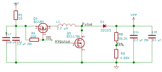
I opened my design schematic and realized I had already designed the Vpp control design. So now I have two options. I used an inductor in the first design to filter the base current of the voltage divider.  In the second design, I just used an RC low pass filter to filter the base current of the transistor.  This project has gone long enough that I am forgetting details of things I have already done.

Prototype Choice:

I prefer the design I did last week to the earlier design. If I find the system doesn’t regulate very well, I may incorporate parts of the earlier design.

Cut in Planning:

Looking at the last schematic and schematic where I want to end up, I can see I need to remove Q4, 5, R6 and R9. I then need to attach pin 1 of the FAN5331 to Pulse. Pin 2 to GND, Pin 3 to Vps. Pin 4 and 5 to the supply side of L1. Short Q4 Pin2 to 3. Finally replace R9 with a transistor with filter to HVPulse.

Continue reading

Refactoring

Update:

No new information on the ADC feature request on Espressif”s forums.

Side Project:

I have started layout of the SSD1332 Breakout PCB.  I finished the layout and ordered PCBs from OSHPark.  Based on the datasheet for the SSD1332, I can get significantly better performance by using it in one of the 8 bit bus modes.  Someone suggested that I look at STM32 processors to drive the display with.  I will be considering that option this week.

Better Firmware:

Continue reading

Easy SDK Upgrade

Update:

I started the upgrade to the newest version of the SDK.

Process:

Upgrading went pretty smoothly.  I had previously downloaded the newest SDK. So I made sure there wasn’t a newer version.  Next I extracted the SDK folder from the downloaded zip file.  I renamed the old folder to indicate it’s version number. I renamed the new SDK folder to Uprogrammer. I copied the code folder (Uprogrammer Firmware) from the old SDK folder into this new one.

Then I compiled (Success), Uploaded (also success after I copied esptools folder), and interacted with the application over serial (again success). Everything seemed to be going great.

Then I opened Eclipse… It didn’t find the project.  So I set my file manager to show hidden files.  I noticed the .metadata folder was not in the new directory. I copied it and still no joy.  I did this for all of the hidden files and it still didn’t work.  I then realized I must not have gotten the spelling of my folder correct.  I checked, the ‘p’ in the folder name needed to be capitalized.

Finally, I checked Git-Cola to see if it worked correctly.  It came up and showed me a bunch of untracked files that were generated by the build I had just done (another success).

This was a very easy upgrade.

The request:

Continue reading

Vpp Control Loop (Firmware V00M)

Plan:

This week I decided to work on the control loop. I decided to add a simple adjustment scheme to the 5 mS system timer event. And then create a way to change the required voltage in increments of 0.1 Volts starting at 10.0

Implementation:

I created a local “static” variable in the events.c file for the target voltage. I then created a function to set this variable target_voltage and another function to get the value of target_voltage.  I then added a simple if statement into the 5ms event that increments the duty cycle of the Sigma Delta if the measured value is too low and decrements it otherwise.  I compiled and tried this, Vpp is ugly.

pic_42_3 Continue reading

ADC analysis (Firmware V00L)

Update:

I forgot to post last week.  If you read this regularly, I am sorry.

Espressif has released a Version 2.0 of it’s SDK.  I am not quite ready to upgrade to that yet, I will wait until after I get my basic functionality tested.  Also, this is a major release, they might have added a few bugs, I can wait till some are fixed.

Voltage Control loop:

I decided to work on the voltage control loop. First step, get a better understanding of the ADC.  I needed to know if the system calls to read the ADC are blocking or nonblocking. An ADC takes time to finish. If it returns the sample from the previous call, I will have to take a second reading to get the correct value.  If it is blocking, I don’t want to call it from within the interrupt service routine (ISR).

Note:  When you call a blocking function, it finishes it’s job before coming back.  Non blocking starts the job and then comes back.

The SDK API is not specific as whether the system_adc_read() is blocking or not.  So I set up a test. Pin 10 of the programming connector connects back to GPIO14.  If I set GPIO14 high before calling system_adc_read() and set it low before calling it again, I can tell how long the call takes. I created a system timer event in events.c and used it to read the adc.  The system timer just calls an os task so it isn’t like an ISR.  I created a function called adc_read.  I initialized a variable, set GPIO14 high, call system_adc_read() and set GPIO14 low. I then set up the function to enable the timer task, I called it init_adc_timer().  I called this from user_init().  The code built. I uploaded it. I hooked up my scope to Pin 10 of the target header.

I got nothing, I didn’t hook up Vtarget.  I decided it was easier to probe GPIO14 directly on the ESP-12F. The pin was always high.  I checked the pin configuration in user_main.c. Nothing wrong there. I found a copy/paste error in events.c  I had copied the line to change GPIO13 to low and changed it to GPIO14 to set it high but didn’t change the one to set it low.  I fixed this and tried again.  I got the pulses I was looking for on the Oscilloscope.  The high pulse width measured 96.2 μS.  This is much longer than I would put into an ISR.  If i polled this read regularly, It would cause a significant loss in performance.

The Next Step:

I decided to see if I could access the ADC directly through hardware registers.  I couldn’t find any clear documentation on the ADC registers.  In the API, there is also a function call system_adc_read_fast().  This one requires wifi to be turned off when called.  I decided to try it turning Wifi off and back on after around each read.  I modified the code to try this change. Now the pulse width is 21.8 μS. Unfortunately, the wifi disconnects when I disable it. This is a problem.  I tried leaving the wifi enabled and it works. 21.8 μS is longer than I would want in an ISR so I will call it from the os_timer function and use it to make adjustments.  If I call this every 5 mS, it will tie up the processor for about 1/2 of 1% of the time.  This doesn’t seem like a lot, but I want to get as much performance as I can when I am programming a target.  And this control loop will have to be running while programming a target.

Conclusion:

The results of my testing are not as good as I had hoped.  Maybe Espressif will come out with a non-blocking way to use the ADC in the future. Ideally, I would call a function to start the conversion, and the system would call back to my function with the result. As a final step I display the menu with the adc reading once every 200 cycles (1 second).  I have uploaded these changes to github click the link in the right column to go check it out.

Do you have any experience with the ESP8266 adc?  Have you found a work around for the blocking call?

Vpp regulation (Firmware V00K)

Update

Neither the PCBs or components have arrived yet.

The decision

This week I decided to work on the Vpp feedback loop. I am interested to see how well the system can regulate the boosted voltage operating on an interrupt driven control loop.

Testing

I needed to see if I could get reliable numbers back from the ADC while generating a given voltage.  First step then was to make it so I could change the state of the analog switch from the serial console.  I used the keys ‘<‘ and ‘>’ to select which input I would be connected to the ADC. I wasn’t sure which signal would be connected to the ADC, So I made sure I could select each one individually. Typing < into the console sets GPIO15 to low and typing > sets GPIO15 high. While setting this up, I discovered that GPIO2 wasn’t configured correctly like I had thought.  I fixed this and added the little bit of code to give me control and tried it.  It built and uploaded without a hitch.

Failure

The code was running, ready to test. I hooked up my oscilloscope to watch the output of the Vpp pin to compare to the analog readings.  When first hooked up, the scope was reading 4.8V and the ADC gave me a result of 15. (ADC should give a result of approximately 230.) I hit the > to see and I got a result of 24.  (off by a factor of 10).  I decided to see if that would hold. I played with the Sigma delta till I got an output around 10 volts. I landed at 10.8V.  At this voltage, the ADC result was 24(no change).  This was disappointing. I hit the < key and read out the ADC with result of 20. Not what I was looking for. (expected something either twice the original value of 15 or 512)  The results are not what I had expected(fail).

Diagnostics

Continue reading

ADC and PWM V00D

I have implemented the Reading the ADC from a keystroke (R) sent over serial. I have implemented the PWM on GPIO12.  My initial testing of the PWM has a lot of jitter and didn’t perform at the frequency I configured.  I want to set up a Hardware PWM and see how it performs.  Jitter and frequency can be important when running a switching power supply, so I want to get this right. I set GPIO2 high to select Target voltage as the input to the ADC and set a variable power supply at 0.3 volts tested it and got results around 300, then set it to 0.5 volts and got ADC results around 500 indicating it’s working as expected.

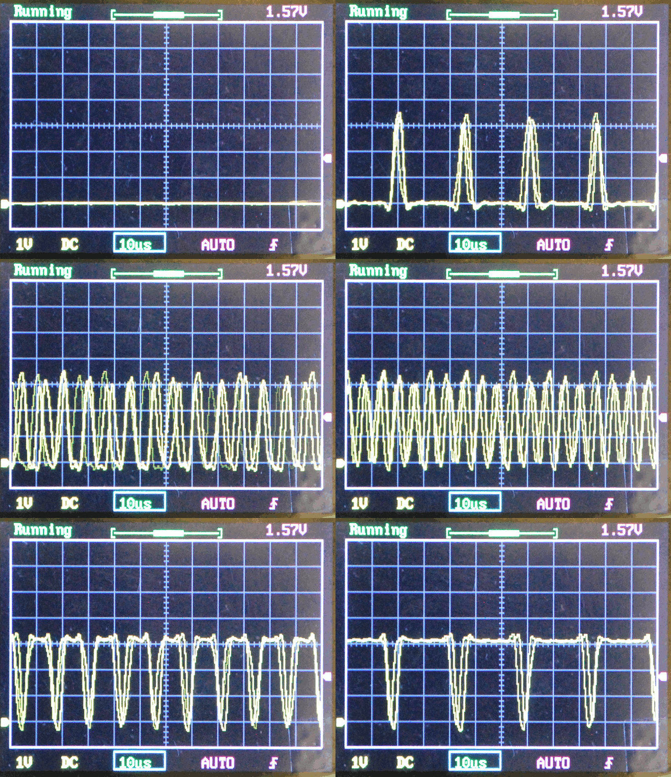
The chip doesn’t have a PWM instead it has a built in sigma-delta pulse generator.  It creates a stream of pulses to achieve the specified duty cycle by adding more pulses to fill in the middle. The chip will connect the sigma delta generator to any GPIO pin I choose.  I can use any free pin to drive the boost inductor switch. If I optimize the inductor for the width of the pulse, I should get very efficient voltage conversion.

There is no API configured for the Sigma Delta unit.  I had to write directly to the registers that set the pin connection and the Sigma Delta unit.  I had to do a lot of experimentation to understand how to set up the Sigma Delta pulse generator.  There is a piece of example code on Espressif’s forum that doesn’t work correctly, but gave me the information I needed to figure out how to configure the unit.  The example code tries to be very generic, and my code is over-simplified for testing.

SigmaDelta