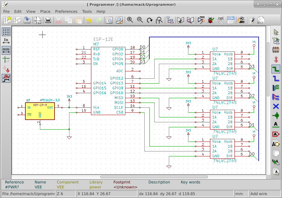
As I start connecting signals on the schematic, I look at which pins have dedicated functions. The dedicated functions I need, I handle first. This allows me to adjust the rest of the design around the required elements. To make the schematic easier to read, I try to avoid crossing traces.
I went into the library editor and moved the pins of the ESP-12E around to make it easier to read the schematic.
I have connected the SPI pins from the ESP-12E to the level shifter chips. I have also connected four GPIO pins to the level shifter chips. I have placed the 3.3V power connections to each of the level shifter chips and the ESP-12E. I have also tied the 3.3V regulator to the 3.3V power bus. I connected GPIO0, GPIO2, GPIO4, GPIO5 to the direction pins of the level shifter chips. I have also connected Vt to the level shifter chips. this voltage will come from the target to be programmed.
I have ordered 5 ESP-12E boards from Ebay. I should receive them within 30 days. Once I receive them, I will start doing a basic hello world project.