Testing Vpp control

Setting up:

It’s been a while since I have worked with the board powered up.  I hooked up the lithium cell and USB cable to my Computer, then the charger started doing it’s job. I then started the serial terminal on my computer.  I hooked up my Oscilloscope to watch Vpp live during testing.

The code still in the board tries to regulate Vpp according to the reading it gets from the ADC.  This isn’t working well.  Since It’s been a while, I built and re-uploaded the project without any changes. This reminded me how I had the tools set up. Of course, the behavior of the board didn’t change with this upload. Next, I disabled the feedback loop to do my testing.

Voltage verses duty cycle:

Continue reading

Cutting in the Vpp prototype

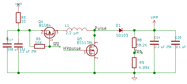
I opened my design schematic and realized I had already designed the Vpp control design. So now I have two options. I used an inductor in the first design to filter the base current of the voltage divider.  In the second design, I just used an RC low pass filter to filter the base current of the transistor.  This project has gone long enough that I am forgetting details of things I have already done.

Prototype Choice:

I prefer the design I did last week to the earlier design. If I find the system doesn’t regulate very well, I may incorporate parts of the earlier design.

Cut in Planning:

Looking at the last schematic and schematic where I want to end up, I can see I need to remove Q4, 5, R6 and R9. I then need to attach pin 1 of the FAN5331 to Pulse. Pin 2 to GND, Pin 3 to Vps. Pin 4 and 5 to the supply side of L1. Short Q4 Pin2 to 3. Finally replace R9 with a transistor with filter to HVPulse.

Continue reading

Vpp Regulation test

Second Thoughts:

I am having second thoughts about co-processor model.  This significantly increases the complexity of the firmware for this design.  I haven’t ruled out any options yet.  If I can get a good voltage for Vpp without the co-processor, I may decide to go back to the level shifter.

Programmatically controlling Vpp:

I have been thinking about how to make an “adjustable voltage” switching regulator adjustable by the microcontroller.  By putting a transistor on the low side of the voltage divider feedback, I believe I can have linear control of the generated voltage controlled by the Sigma-Delta output. I got a basic circuit design from the FAN5331 datasheet. I then replaced the ground side resistor of the feedback voltage divider with an NPN transistor.  I came up with the circuit below.

The FAN5331 has a 1.25 volt reference comparator to decide if it needs to generate more voltage or wait.  With the Sigma Delta input to r3 at 0 out of 255, the transistor will never turn on and the voltage on the feedback will be above the 1.25V threshold and the regulator will effectively shut down.

Resistor Calculations:

Continue reading