Cost review

Newest SDK:

Espressif has moved the SDK to GitHub.  At this point, It is version 2.1.  I have no indication that they have done anything with the ADC Feature I requested.  I have not updated to this newest SDK yet. I will do that before I spend any time working on firmware.

New component costing:

The 74LVC2T45 level shifter chips are US $0.32 each in low quantities.  The PCA9306 I2C level shifter are about US $0.60 each in low quantities.  This results in the costs of the level shift components arount $1.50.  The original single part costs around US $1.25 each in low quantities.  This is not a big difference in cost but it does affect board space.

Design review:

Continue reading

Target interface analysis

Website security:

I have updated this website to default to TLS for connections.  I have a certificate supplied by my hosting provider.  I have also turned on member accounts.  I am hoping this will make it more convenient you, the readers to join the conversation.

Voltage level shifter:

I am still trying to decide the best way to go for adjusting to the target platform voltage.  SPI typically needs 3 bits output (SS, SCLK, MOSI) and one bit input(MISO)  Sometimes SPI needs more. JTAG needs 4 pins output(TCK, TMS, TDO, TRST) and one bit input(TDI). I found the JTAG signal description on this page. I2C needs two bits of bi-directional open drain signals.  I don’t know of any MicroControllers that can be programmed over I2C but there are flash memories that are programmed that way.

Based on this information, I can see that I would want 4 bits of output and 2 input along with a 2 bit open drain bi-directional.  This gives me a total of eight bits of data available to connect to the target device.  In addition to that, I need Target Vcc and GND and Vpp. Continue reading

Schematic update

Arduino compass toy:

I have had a little time to play with the OLED panel this week. Unfortunately, I still can’t get it to work.  I have been trying to get it to work in SPI mode, But I think I now want to try to start working in either 8080 or 6800 modes.

Schematic Update:

I updated the schematic to reflect the results of my testing from 2 weeks ago.

I still need to try a high gain transistor in place of the one I used to see what will happen.

I am waiting to make some decisions before I update the schematic on GitHub.

Decisions:

Continue reading

Modifying the circuit for better Vpp control

Planning:

I needed finer control of Vpp.  Since this is an experimental design, I decided to make some calculated guesses to choose the right values.

To start with, I believe that putting a resistor between the emitter and ground of the feedback transistor will limit the gain of the transistor.  The voltage of this resistor will rise as the current through it increases limiting the current gain of the circuit.  The first guess I tried was calculating the resistor as if the transistor wasn’t there(same as fully saturated) for my max voltage (25 V).

Continue reading

Testing Vpp control

Setting up:

It’s been a while since I have worked with the board powered up.  I hooked up the lithium cell and USB cable to my Computer, then the charger started doing it’s job. I then started the serial terminal on my computer.  I hooked up my Oscilloscope to watch Vpp live during testing.

The code still in the board tries to regulate Vpp according to the reading it gets from the ADC.  This isn’t working well.  Since It’s been a while, I built and re-uploaded the project without any changes. This reminded me how I had the tools set up. Of course, the behavior of the board didn’t change with this upload. Next, I disabled the feedback loop to do my testing.

Voltage verses duty cycle:

Continue reading

Cutting in the Vpp prototype

I opened my design schematic and realized I had already designed the Vpp control design. So now I have two options. I used an inductor in the first design to filter the base current of the voltage divider.  In the second design, I just used an RC low pass filter to filter the base current of the transistor.  This project has gone long enough that I am forgetting details of things I have already done.

Prototype Choice:

I prefer the design I did last week to the earlier design. If I find the system doesn’t regulate very well, I may incorporate parts of the earlier design.

Cut in Planning:

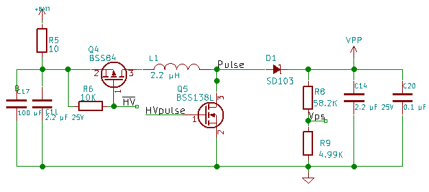
Looking at the last schematic and schematic where I want to end up, I can see I need to remove Q4, 5, R6 and R9. I then need to attach pin 1 of the FAN5331 to Pulse. Pin 2 to GND, Pin 3 to Vps. Pin 4 and 5 to the supply side of L1. Short Q4 Pin2 to 3. Finally replace R9 with a transistor with filter to HVPulse.

Continue reading

Vpp Regulation test

Second Thoughts:

I am having second thoughts about co-processor model.  This significantly increases the complexity of the firmware for this design.  I haven’t ruled out any options yet.  If I can get a good voltage for Vpp without the co-processor, I may decide to go back to the level shifter.

Programmatically controlling Vpp:

I have been thinking about how to make an “adjustable voltage” switching regulator adjustable by the microcontroller.  By putting a transistor on the low side of the voltage divider feedback, I believe I can have linear control of the generated voltage controlled by the Sigma-Delta output. I got a basic circuit design from the FAN5331 datasheet. I then replaced the ground side resistor of the feedback voltage divider with an NPN transistor.  I came up with the circuit below.

The FAN5331 has a 1.25 volt reference comparator to decide if it needs to generate more voltage or wait.  With the Sigma Delta input to r3 at 0 out of 255, the transistor will never turn on and the voltage on the feedback will be above the 1.25V threshold and the regulator will effectively shut down.

Resistor Calculations:

Continue reading

Co-processor decision

The ADC problem as well as cost of the voltage level shifter leads me to think having a co-processor is the best solution.  The last two posts look at 8 bit and 16/32 bit processors I could use for this purpose.  For firmware update, I want the co-processor to have USB capability.  This would allow me to get rid of the USB to serial bridge chip.

The choices:

I ended up with Microchip as the manufacturer for both architectures. The PIC16 line of controllers and the SAM32C21 line of controllers.

Continue reading

16/32 bit Co-Processor Research

Vacation:

I went on vacation last week with my grandson.  I had to finish client work before I could go so two weeks ago I didn’t get a post done and last week, I was spending time with my family. I was hoping to post ahead of time and schedule them out, but it didn’t happen.  Sorry to anyone looking forward to my posts.

ADC Feature Request:

The request I made in the bug report section of the Espressif forum has been viewed 376 times but still no indication that they are working on it.  August 16, 2016 is the last update to the SDK.

MSP430:

Ti makes a great processor line with cloud based tools. Which means they can be developed on any platform.

I had to disqualify the MSP430 line of processors because they all have a max voltage of 3.7 or lower.

STM32:

The STM32 are ARM based architecture chips. They all have a max operating voltage of 3.6V or less. They do have good GCC support so they can be developed on any system. The max voltage issue disqualifies the STM32.

PIC32:

The PIC32 line of chips do not have any devices that run at 5 volts. This disqualifies the PIC32 line from Microchip.

SAM32:

Microchip acquired Atmel recently.  Atmel used to sell the SAM32 ARM architecture line of MCUs.  So Microchip now carries this line of chips.  The ATSAMC2  line all operate from 2.7 to 5.5 Volts.  The 2.7 is a little high on the low side but it is acceptable.  ARM compilers are available on all the major desktop operating systems. The lowest marketing price for this line of chips is US $1.36.  The smallest flash available is 32KBytes which should be far more than enough for this project.  This chip runs at 48 MHz.  Which should be fast enough.  It also has 32 pins which should be enough IO.  The ATSAMC21E15A is a strong candidate.

Other Controllers:

Do you have any suggestions for 16 or 32 bit Micro Controllers?  Are there any you would like me to look at for this project?

8 bit Co-processor Research

Seeed Studio:

Seeed Studio has asked that I put a link to their site on this blog.  I have used Seeed Studio Fusion service and I was/am satisfied with them. So I have added a link in the right hand column.

This Week:

I decided to research potential processors for the level converter circuit.

Wikipedia has a list of common microcontrollers. This is a good resource when looking for possibilities.  I will only look at a few processors from companies I am familiar with. If this co-processor chip is going to act as a level shifter, It needs to be able to drive and accept 5 Volts.

STM8:

ST Microelectronics makes STM8 and STM32 lines of processors. I will look at the STM32 line next week when I research 32 bit controllers.

The STM8 line has many processors that have a max operating voltage of 5.5 Volts.  Of the processors that can operate at 5.5 Volts, the lowest operating voltage is 2.95 volts.  This might be high for some ARM systems I would want to support.  ST Microelectronics supports their devices very well on Mac and Windows.  There is a good open source compiler available for Linux called Small Device C Compiler(SDCC). The STM8 line of chips doesn’t have any built in USB capabilities. The STM8 is a possibility.

PIC16:

Continue reading